


Phaser 8400/8500/8550/8560 Color Printer Service Manual 4-35
General Troubleshooting
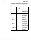
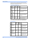
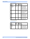
This test drives the Printhead tilt mechanism through one cycle to determine if
it is controllable and operating as expected.
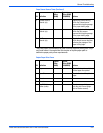
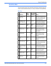
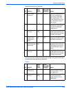
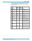
4 Roller Average
Period (sec)
50 to 1600 -.05 to .05 Reports the average period of
the Y-Axis following error
ripple during the Roll With
Both Loaded interval. This
variation would be due to the
dmu roller rolling along the
drum surface.
5 Roller Revs 3 to 40 Reports the number of Y-Axis
following error ripple peaks
during the Roll With Both
Loaded interval.
6 Roller Disengaged
Time (sec)
-0.001 to
0.05
-.05 to 0.5 Reports the time from the
unload roller command to the
engine until the drum indicates
no further roller contact.
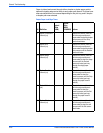
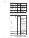
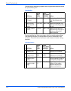
7 Blade loaded
average Y-Axis
following error
(mpts)
-160 to
-50
-800 to
-100
Reports the average Y-Axis
following error during the Roll
With Blade Loaded interval.
8 Blade loaded Y-
Axis following error
ripple (mpts)
-0.001 to
0.50
115 to 900 Reports the difference
between the max and the min
Y-Axis following error during
the Roll With Blade Loaded
interval.
9 Blade Disengaged
Time (sec)
-0.05 to 0.05 Reports the time from the
unload blade command to the
engine until the drum indicates
no further blade contact.
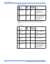
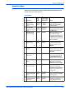
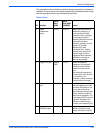
Tilt Drive
R# Definition
Typical
Value
(8400)
Typical
Value (8500/
8550/8560)
Actions
0 Tilt Engage Cap
Position (min)
10 to 600 50 to 550 Reports the distance from the
cap Home position to the tilt
cam engage point.
1 Pre Standby Peak
Location ()
325 to
3100
-125 to 10 Reports the distance around
the tilt cam from the tilt
engage position to the pre
standby peak.
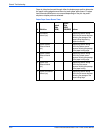
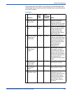
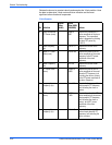
Drum Maintenance Drive (Continued)
R# Definition
Typical
Value
(8400)
Typical
Value (8500/
8550/8560) Actions