


Phaser 8400/8500/8550/8560 Color Printer Service Manual 2-21
Theory of Operation
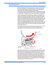
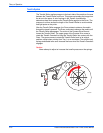
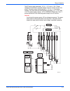
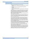
The DC power supply generates + 3.3 V, +/- 15 V, and +/- 50 V. These
voltages provide direct or regulated voltage values to various circuits in the
printer. The power control board regulates +/- 15 V to +/- 12 and other
voltages. The main board also has regulators providing + 5 V, + 2.5 V, and +
1.8 V. The power supply outputs + 3.3 V in ENERGY STAR mode. Fuse F1
provides protection for the switching power supply in the DC section.
W
arn
i
ng
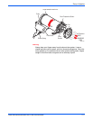
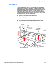
Do not touch the power supply; AC line voltages are present. The power
switch does not disconnect power from the printer. The power switch
signals the supply and the printer logic to begin a shutdown sequence.
F3
F2
S1
AC Line
AC Neutral
Line
Gnd Ref
Neutral
D
r
u
m
I
n
k
4
I
n
k
3
I
n
k
2
I
n
k
1
r
e
s
2
r
e
s
1
js
r
js
I
P
r
e
h
t
H
8
H
9
H
1
3
H
1
2
H
1
1
H
1
0
H
4
H
3
H
2
H
1
AC Line
AC Neutral
Low
Switcher
+3.3 V
+15 V
-15 V
+50 V
-50 V
H13
H12
H11
H10
H9
H8
H4
H3
H2
H1
uProcessor
REG
Vss
Vcc
Serial
Control
Interface
s8500-022