


2-10 Phaser 8400/8500/8550/8560 Color Printer Service Manual
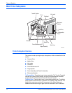
Theory of Operation
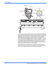
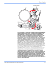
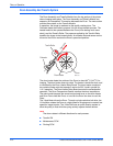
Printhead Tilt
The Printhead is able to rotate into four basic positions:
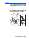
1. Printhead lock / ship position (19.5 degrees): The Printhead restraint pins
are resting against the right and left locks. In this position, the Printhead
tilt arm/follower is free of the tilt cam, and the head is secured for
shipping.
2. Wipe position (12 degrees): The Printhead tilt arm/follower is engaged
with the tilt cam, and the head overload spring contact is engaged with
the overload spring-plate to provide the correct force for the wiper.
3. Standby position (20.9 degrees): Allows the wiper to clear the Printhead
in order to be in the start wipe Printhead position, and also allow the
Printhead locks to pivot and lock or unlock the Printhead. In this position,
the Printhead tilt arm/follower is engaged at the standby position of the tilt
cam.
4. Print position (0 degrees): The Printhead is forward and resting against
the right and left head-to-drum buttons. The head-to-drum buttons define
the space between the jet stack and the drum.
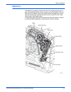
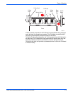
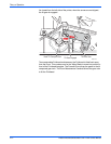
The tilt cam tilts the head into the basic four positions listed above. The cam
has five special features and associated functions:
1. The cam is combined with a missing tooth gear that allows the cam to be
inactive in the print position, which frees the process drive to perform
other printer operations.
2. The cam has a latching feature to unlatch and latch the missing tooth gear
to engage the Printhead tilt drive train.
3. The cam profile has a standby dwell (the portion of the cam that has a
constant radius), that holds the Printhead back in the standby position.
4. The cam profile has a wipe dwell the holds the Printhead back in the wipe
position.
5. The cam profile increases the power consumption at a specific phase of
rotation. This allows the software to identify a power consumption
footprint that alerts the printer to a fault when the head is locked in error.
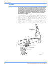
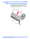
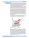
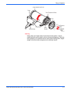
The Printhead is tilted away from the drum and locked for shipping. The
Printhead is locked if the head lock indicator is above the level of the output
tray. When the Printhead is locked in the shipping position there are three key
restraining elements:
1. The Printhead is restrained from rotating from the shipping position by
pins extending from both ends of the Printhead into a pocket. These
pockets are defined by dampening pads that limit motion to the lockarms
that pivot into the lock position, limiting forward motion toward the drum.
The wiper carriage holds the locks in the lock position, which are normally
spring-loaded in the unlocked position.
2. The Printhead is restrained at the X-Axis shafts by the right and left head
restraints that limit motion at both ends of the Printhead.
3. The Printhead is limited to the nominal motion of 1.7 mm in the X-Axis
(left / right side motion when the Printhead is back and locked) by the right
lock and the left home stop on the left side frame.