


8-30 Phaser 8400/8500/8550/8560 Color Printer Service Manual
Service Parts Disassembly
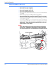
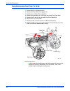
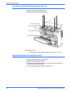
8. Align the clevis on the Transfix Load Arms with the holes in the mounting
ears on the Drum. The Transfix Load Arms point in the opposite direction
from the Drum Thermistor. Ensure that the cam followers on the Transfix
Load Arms are under the Transfix Cams.
9. Insert the clevis pins through the clevis and the mounting ears on the
Drum (pins are inserted from the outside). Ensure that the o-rings are
mounted on the inside end of each clevis pin.
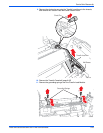
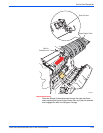
10. Align the Exit Module to the chassis and route the Drum Temperature
Sensor harness through the opening in the Exit Module that the other
cables pass through. Seat the Exit Module on the two front locating pins
and then on the rear locating pins.
11. Insert and torque the four screws securing the Exit Module to 15 in.-lbs.
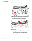
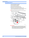
12. Apply a small quantity of Rheolube 768 grease (P/N 070E00890) to the
spring hook’s groove of the Transfix Load Arms.
Note
Ensure that you lever the spring cam towards the center. Applying the
pressure in the wrong direction can damage the Transfix Load Module
(see the figure on page 8-22).
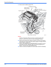
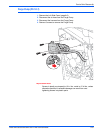
13. Insert a T-20 Torxbit through the right side slotted hole in the Transfix
Load Module, engage the hole on the back of the module, and lever the
module’s spring cam toward the center of the printer while connecting the
spring hooks to the Transfix Load Arms. Repeat for the other side.
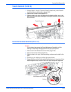
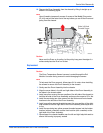
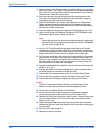
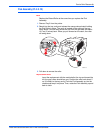
14. Pull the lower end of the Y-Axis spring arm toward the front of the printer
and install the Y-Axis Belt first on the motor pulley and then on the Drum
pulley. (It is not necessary to align the belt on the Drum pulley.) Ensure
that the grooves of the belt align in the grooves of the motor pulley and
that the cross-ribs are away from the pulleys.
15. Reposition the Media Drive Assembly, insert the 3 screws, and torque the
screws to 12 in. lbs.
16. Connect the Media Drive Fan and Media Drive motor harnesses. Bend
the cable retainer as required to hold the fan cable.
17. Connect the Drum heater harness to the Drum Heater Relay Board.
18. Connect the Drum encoder harness to the Power Control Left Cable.
19. Connect the Drum Temperature Sensor harness to the I/O Board.
Caution
The Drum Temperature Sensor harness is routed through the Exit
Module. Use care during removal to avoid damaging the sensor.
20. Connect the Exit Module Cable to the I/O Board.
21. Ensure that the Drum heater and encoder harnesses are dressed
correctly and secured by the retainer hook at the Process Drive.
22. Reinstall the Drum Fan and secure it with 3 screws. Torque the top screw
into the Labyrinth Seal to 20 in. lbs. and the other two screws into the
chassis to 12 in. lbs.
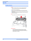
23. Pass the Stripper Blade Solenoid harness through the right side of the
chassis and seat the Lower Inner Duplex Guide on the four mounting pins
on the chassis.
24. Install the Ink Loader (page 8-7).
25. Reinstall all covers and doors.