


Phaser 8400/8500/8550/8560 Color Printer Service Manual 2-3
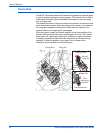
Theory of Operation
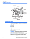
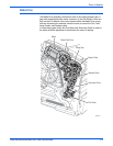
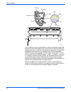
The Ink Loader: Stores and melts the ink. The melted ink drops into the
Printhead ink reservoirs underneath the ink loader.
The Printhead: Delivers ink onto the drum surface to create an image. The
Printhead includes 1236 interleaved jets (309 of each primary color) to
provide the ability to electronically turn off a weak or missing jet to restore
image quality.
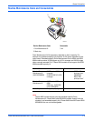
The Drum Maintenance Kit: Creates a thin layer of silicone oil on the surface of
the Drum prior to printing. The oil keeps the ink from sticking to the Drum’s
surface and facilitates image transfer to the media.
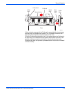
The Purge System: Uses air pressure and a wiper blade to remove any debris
or air bubbles that may be obstructing the Printhead nozzles.
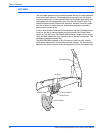
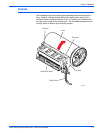
The Drum Assembly and Transfix System: Form the key portion of where
imaging takes place. The image is first printed as a "mirror" image on the
rotating Drum. A sheet of warmed media feeds from the Preheater and
passes between the Drum and the Transfix Roller. The Process Drive gear
train then loads the Transfix Module and presses the media to the Drum to
adhere the image as the Drum spins in the transfix direction.
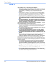
The Electronics System: includes the Electronics Module (also known as the E-
can); which contains the main board, the image processor board, the power
control board, and the power supply board. Distributed in the print engine are:
the Wave Amplifier, I/O board, and Drum Heater Relay Board.