


Phaser 8400/8500/8550/8560 Color Printer Service Manual 8-27
Service Parts Disassembly
Drum Assembly (PL2.0.3)
1. Remove the Front Door (page 8-4).
2. Remove the Right Side Cover (page 8-5).
3. Remove the Left Side Cover (page 8-5).
4. Remove the Exit Cover (page 8-6).
5. Remove the Ink Loader (page 8-7).
6. Remove the Lower Inner Duplex Guide (page 8-33).
7. Place the Printhead in the park position (tilted back) and the Wiper
Assembly in the home position (all the way down).
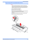
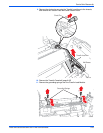
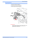
8. Insert a T-20 Torxbit through the right slotted hole in the Transfix Load
Module, engage the hole on the back of the module, and lever the
module’s spring cam toward the center of the printer to release/unhook
the spring hooks from the Transfix Load Arms. Slowly relax the lever to
return the spring cam to the relaxed position. (See the figure on
page 8-22.) Repeat for the other side.
N
o
t
e
Ensure that you lever the spring cam towards the center. Applying the
pressure in the wrong direction can damage the Transfix Load Module.
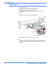
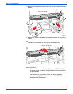
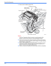
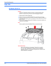
9. From the right side, remove 3 screws from the Drum Fan and allow the fan
to hang free.
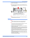
10. Relieve tension on the Y-Axis Belt by pulling the end of the spring arm
toward the front of the printer using your fingers. See page 8-8.
11. Slide the belt off the pulley.
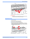
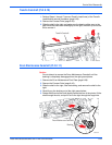
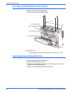
12. Unplug the Drum heater cable from the Drum Heater Relay Board and
free the cable from the retaining hook.
13. Unplug the Drum encoder cable connector from the Power Control Left
Cable and free the cable from the retaining hook.
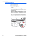
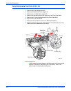
14. Unplug the Drum Temperature Sensor connector from the I/O Board.