


Phaser 8400/8500/8550/8560 Color Printer Service Manual 8-3
Service Parts Disassembly
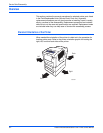
General Notes on Disassembly
Caution
Follow the steps of all disassembly procedures in the order given to avoid
damaging printer components.
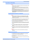
1. Before servicing the printer, switch Off the printer power, wait until the
printer completely shuts down, and disconnect the power cord from the
wall outlet.
2. Wear an electrostatic discharge wrist strap to help prevent damage to the
sensitive electronics of the printer circuit boards.
3. Upon reassembly of printer components, be sure the components are all
in their home positions, otherwise damage to the printer will occur. See
Chapter 6 Adjustments, Home Position page 6-2 for information on the
home positions.
Special Notes Regarding Screws Used in This Equipment.
Caution
Screws in plastic are torqued to 12 in. lbs., metal to 15 in lbs., unless
otherwise specified. The screws for the Printhead Restraints should be
torqued to 6 in. lbs. Irreversible damage can result from over tightening
the screws into plastic parts.
■ Always use the correct type and size screw; coarse thread, brass-colored
screws into plastic and fine thread, silver-colored screws into metal.
■ Using the wrong screw can damage tapped holes. This applies to the
yellow reverse-threaded screws on the Drum.
■ Do not use excessive force to remove or install either a screw or a printer
part. If using a power driver to install a screw into plastic, start the screw
by hand.
■ If you strip out threads in the plastic chassis, a silver-blue-tinted thread
repair screw (included in the hardware kit) can be used to correct the
problem.
■ If you remove a silver-blue-tinted thread repair screw during disassembly,
replace the screw the same location or additional damage to the printer
will occur.
W
arn
i
ng
Unplug the AC power cord from the wall outlet before removing any
printer part.
Notations in the Disassembly Text
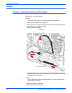
■ The notation “(item X)” points to a numbered callout in the illustration
corresponding to a part or step being performed.
■ The notation “PLX.X.X” indicates that this component is listed in the
Service Parts List.
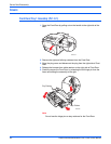
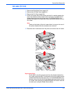
■ Bold arrows in an illustration show direction of movement when removing
or replacing a component.