


2-20 Phaser 8400/8500/8550/8560 Color Printer Service Manual
Theory of Operation
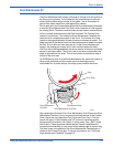
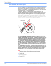
Information stored on the Configuration Card includes the feature value,
ethernet address, and personality parameters. The card reads a combination
of feature values and the printer hardware capabilities; this will determine the
printer model configuration.You can migrate the Configuration Card from one
printer to another to transfer the printer configuration. Feature value and
ethernet address are configured at the factory, and are “read only”. The
feature value is fixed in the Configuration Card and does not change. Ethernet
address is stored only on the Configuration Card and cannot be rewritten. The
Ethernet address is not written to the NVRAM chip.
Personality parameters are a subset of network configuration parameters,
which are populated to the Configuration Card when the customer configures
the printer. The personality parameters are copied (“shadowed”), from the
main board's NVRAM chip to the Configuration Card during the normal
operation of the printer. When the configuration card is inserted into a new
printer, the personality parameters on the Configuration Card are written into
the NVRAM chip of the new printer. When a printer is powered on, if it
contains the Configuration Card of another printer, the personality parameters
copy automatically to the NVRAM chip. When removing the Configuration
Card for the Phaser 8400, the printer reboots as a B (non-networking)
configuration. Refer to the “Configuration Card Personality Parameters”
section at the end of this chapter for a detailed list of “shadowed” personality
parameters.
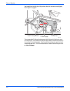
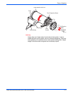
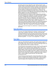
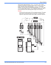
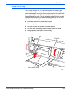
Power Control Board
The power control board distributes drive voltages to operate the printer’s
various motors, solenoids, and clutches. The power control board also
provides the interface that returns information from the printer's sensors to the
main board. The sensors track mechanical and thermal functions, such as the
position and temperature of the Printhead. The power control board also
generates regulated +/- 12 V and 5 V from unregulated +/-15 V power.
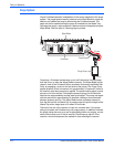
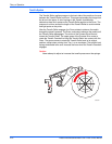
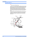
Power Supply
There are no field adjustments necessary on the power supply. In general, the
power supply has two main sections: the AC section and the DC section. In
the AC section, power routes to 10 triacs. Under main board logic control, the
triacs supply AC power to the 10 heaters in the printer.
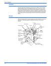
Two fuses provide current protection to the triacs. Fuse F2 and F3 protect the
power supply from a shorted triac from a defective heater. If the F2 or F3
fuses blow, it is best to replace the Electronics Module (and, of course, the
defective heater), rather than the fuse. With the fuse replaced but the triac
shorted, AC power may be applied to the heater. However, each time the main
board turns on a triac to activate a heater, it is turned on for only a fraction of a
second. The main board must constantly re-address each heater it wants to
control. If the print engine firmware should fail, the heaters would
automatically shut off.
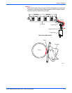
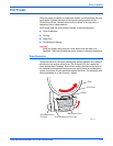
Thermal fuses also protect the printer. A thermal fuse opens in the unlikely
event of a “runaway” heater following a hardware failure. The Drum and the
Preheater thermal fuses are located on the Preheater. Additional thermal
fuses are located on the Printhead and on the ink melting elements.