


Phaser 8400/8500/8550/8560 Color Printer Service Manual 4-63
General Troubleshooting
n. If the Electronics Module, I/O Board and Control Panel are working,
the error code 34,001.43 should appear on the display to indicate the
Printhead is disconnected. If the correct error code is displayed,
continue with the next steps of the procedure.
If the correct error code is not displayed, replace the Control Panel
and I/O Board and verify the correct error code appears. Retest
Electronics Module, I/O board, Control Panel combination.
If no error code displays, return the original Control Panel and I/O
Board to the printer. Replace the Electronics Module and then
continue with the next steps of the procedure.
o. If a different error code is displayed, see the “Fault Code Error
Message Troubleshooting” on page 3-7 for a definition of the problem
and the procedures needed to solve the problem.
2. Repeat these procedures to check all circuits connected to the I/O Board:
a. Turn off printer and wait 30 seconds for power supply capacitors to
discharge.
b. Plug in the I/O Board connectors, one at a time, and perform steps C
and D for each connector.
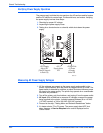
c. Turn on printer and wait for the error code 34,001.43. Check that the
three voltage indication LEDs inside the Electronics Module (visible
through the vent holes of the Electronics Module near the AC power
switch) are lit.
d. If the proper error code and LED doesn't appear after each I/O
connector is reconnected, repair or replace the faulty circuit.
e. If the proper code appears, repeat the procedures until all I/O board
connectors are plugged back in.
f. If repairs are made during this step, plug in all connectors to printer
and retest. If printer is fixed, reattach covers to printer and perform a
full test. If no defects are found in this step, continue with next step.
3. The proper error code is displayed, repeat the following procedures to
check all circuits connected to the Electronics Module:
a. Turn off printer and wait 30 seconds for power supply capacitors to
discharge.
b. Plug in the connectors, one at a time, and perform steps C and D for
each connector.
c. Turn on printer and wait for the error code 34,001.43. Check that the
three voltage indication LEDs inside the Electronics Module (visible
through the vent holes of the Electronics Module near the AC power
switch) are lit.
d. If the proper error code and LED doesn't appear after each I/O
connector is reconnected, repair or replace the faulty circuit.
e. If the proper code appears, repeat the procedures until all I/O board
connectors are plugged back in.
f. If repairs are made during this step, plug in all connectors to printer
and retest. If printer is fixed, reattach covers to printer and perform a
full test. If no defects are found in this step, replace Electronics
Module, test printer, reattach covers to printer and perform a full test.
Verifying Print Engine Operation by Printing Stored Pages
1. Turn On the printer. If the printer does not begin initializing, go to the topic,
“Measuring AC Power Supply Voltages” on page 4-64.
2. Once the Power light is on (not blinking) and the Control Panel displays
Ready to Print it is now possible to print a stored page.
3. If a page prints, the print engine is working correctly. If not, a problem
exists with the print engine.