


Phaser 8400/8500/8550/8560 Color Printer Service Manual 4-65
General Troubleshooting
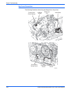
Detecting condition of Fuse F2 and F3
1. The Drum and Preheater connect to F3.
2. The Printhead and Ink Loader connect to F2.
3. Turn the power switch Off and wait for the printer to shut down.
4. Unplug the Power Cord.
5. Remove the Ink Loader (page 8-7).
6. From the back of the printer you will see one heater cable connector on
the left near the power switch and two under the ink loader.
7. Place the power switch in the On position and make the following
measurements:
a. Using an ohmmeter, measure the resistance between the lowest pin
on the left side, just above the power switch, and the lowest pin on the
AC input connector. If the meter measures 0 ohms, F3 is intact.
b. Measure between the right most pin under the ink loader and (again)
the lowest pin on the AC input connector. If the meter measures 0
ohms, F2 is intact.
8. The heater triacs are not accessible for measurement and are
disconnected from loads if the switch is off or the printer is powered down.
9. Reinstall the Ink Loader following the test.
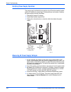
Measuring DC Power Supply Voltages
1. Check the power supply status LEDs, they should be bright.
2. If the printer is operational, use the diagnostic test Monitor Voltages.
N
o
t
e
DC voltage test points can be found on the power control board. When
you remove the rear access cover, you will see the test points below the
RAM DIMM’s on the power control board.
Ensuring Ground Integrity
Intermittent or missing ground connections can result in minor interferences in
the printer. As examples:
■ Control Panel display can be affected (blank)
■ I/O board errors
■ False jam reporting
■ Erroneous thermistor readings
■ Major interruptions
■ Damage to the electrical boards