


4-56 Phaser 8400/8500/8550/8560 Color Printer Service Manual
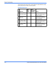
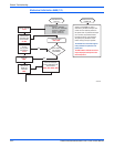
General Troubleshooting
Miscellaneous Electrical Troubleshooting
The Electronics Module contains the power supply, image processor board
and the power control board. If a component of the Electronics Module fails,
and service is necessary, the entire Electronics Module is replaced as a unit.
No individual board troubleshooting is required. The printer contains many
self test routines to aid in diagnosing problems.
N
o
t
e
If the printer encounters certain fault conditions, the printer may reboot up
to three times before displaying an error code. This is an attempt to
correct the problem and reduce the number of unnecessary service calls.
Following the suggested debug procedures, the specified sequence generally
provides better test coverage than performing tests in a different order.
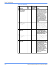
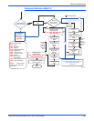
Error Message Displayed on Control Panel LCD
Printer has detected a fault condition. See “Fault Code Error Message
Troubleshooting” on page 3-7 for definitions and solutions.
Blank Display and the PS and PE LEDs Are Flashing an Error Code
Printer has detected a fault condition but can't display a message on the
LCD. Some portion of the chain of devices used to drive the LCD may be
defective since an error message is not displayed. See “Fault Code Error
Message Troubleshooting” on page 3-7 for definitions and solutions.
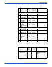
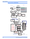
Printer Fails Power-Up: PS, PE and 3.3 V LEDs Do Not Illuminate
Printer is not receiving proper AC.
Caution
Use caution with hazardous voltages when diagnosing AC problems. The
3.3 V LED is located inside the Electronics Module and must be observed
through the vent holes close to the AC power switch, see the illustration
on page 4-64.
1. Inspect the power cord.
a. Verify AC outlet voltage and current capacities are within
specifications.
b. If necessary, move the printer to a different outlet and retest.
2. Transient on AC line tripped protective circuitry in printer power supply.
Cycle power to printer to reset protective circuits in power supply.
3. Short circuit on 3.3 V supply within the Electronics Module. ESD damage
to the printer may occur if static electricity is discharged to printer
electronics
a. With power cord connected, touch the metal Electronics Module to
discharge any static electricity.
b. Turn off printer and wait 30 seconds for power supply capacitors to
discharge. Damage to circuits within the Electronics Module may
occur if the power supply capacitors are not allowed to fully
discharge.