


4-58 Phaser 8400/8500/8550/8560 Color Printer Service Manual
General Troubleshooting
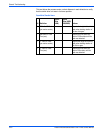
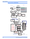
■ Inkload Signal J910
■ DMU Sense J860
■ Drum Thermistor J870
■ Exit Module J680
■ Heater Relay Control J950
c. Retest the resistance of the I/O board. If the resistance is still less
than 1K ohm, replace the I/O board, reinstall all cables and retest
printer.
d. If the I/O board resistance is OK, plug in the I/O board connectors one
at a time and retest the resistance.
e. Plug in all cables removed during service.
f. Trace through all service steps performed to reattach any cables that
were unplugged during debugging.
g. Attach printer covers.
h. Perform full test of printer.
6. Short circuit on 3.3 V power supply within the Control Panel.
a. Required: Follow all procedures from Step 3 and Step 4 before
proceeding.
b. With power cord connected, touch the metal Electronics Module to
discharge any static electricity.
c. Turn off printer and wait 30 seconds for power supply capacitors to
discharge. Damage to circuits within the Electronics Module may
occur if the power supply capacitors are not allowed to fully
discharge.
d. Plug in the Control Panel connector J220 on the I/O board. This step
adds the Control Panel back to a working Electronics Module and I/O
board in order to see if the short circuit is also removed.
e. Turn on power to the printer.
f. If the PE and PS indicators do not flash momentarily, the short is on
the Control Panel. Replace the Control Panel and retest the printer.
Skip the rest of this section if the PE and PS indicators flash because
the problem is elsewhere in the printer.
g. Plug in all cables removed during service.
h. Trace through all service steps performed to re-attach any cables that
were unplugged during debugging.
i. Attach printer covers.
j. Perform full test of printer.
7. Short circuit on 3.3 V power supply within the printhead.
a. Required: Follow all procedures from 'Short circuit on 3.3 V power
supply within the Electronics Module' before proceeding. The
following procedure relies on a working Electronics Module to
determine if the printhead is causing a short circuit.
b. With power cord connected, touch the metal Electronics Module to
discharge any static electricity. ESD damage to the printer may occur
if static electricity is discharged to printer electronics.
c. Turn off printer and wait 30 seconds for power supply capacitors to
discharge. Damage to circuits within the Electronics Module may
occur if the power supply capacitors are not allowed to fully
discharge.
d. Plug in the printhead interface connector (J130) to the Electronics
Module. This step adds the Control Panel back to a working
Electronics Module and
I /O board in order to see if the short circuit is
also removed.
e. Turn on power to the printer.