


Phaser 8400/8500/8550/8560 Color Printer Service Manual 3-3
Error Messages and Codes
Power-Up Error Messages and LED Codes
The printer has three sets of tests that are run when first powered on:
■ Built-In Self Tests (BIST)
■ Power On Self Tests (POST)
■ Print Engine Self Tests (PEST)
Note
BIST and POST errors are not stored in the fault history logs.
BIST Error Reporting
BIST verifies basic Electronics Module CPU operation and reports failures by
utilizing the rear interface panel PS and PE LEDs. These tests occur
immediately at power-up, before POST tests are run or the Control Panel is
initialized.
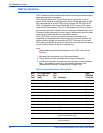
The following table defines the blink patterns associated with a failure.
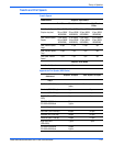
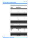
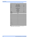
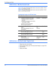
BIST Error Reporting Blink Pattern Definition Table
PE LED PS LED Description
Off or 1
Blink, and
then off
Off or 1
Blink, and
then off
The power supply could not remain regulated when DC
power was applied so it was shut down.
Follow the troubleshooting procedures for electrical shorts
(see
“Miscellaneous Electrical Troubleshooting” on
page 56) and check the power supply fuses.
On Solid
(dimly)
On Solid
(dimly)
Initialization failure. The printer is held in reset mode. This
can be caused by an Electronics Module fault or a +3.3 V
power supply regulation failure (see
“Miscellaneous
Electrical Troubleshooting” on page 4-56). See also,
“Verifying Power Supply Operation” on page 4-64.
Off PS and
Control
Panel 1/2
sec. blink
Boot loader memory test failure. Ensure the printers RAM
chips are properly seated and that the correct RAM type for
this printer is installed.
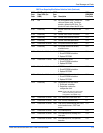
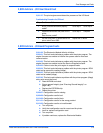
1 Rapid
blinking
CPU bridge and/or PCI bus is not communicating. Reboot
the printer, if the error still occurs, replace the Electronics
Module.
2 Rapid
blinking
ROM not responding. Reboot the printer, if the error still
occurs, replace the Electronics Module.
3 Rapid
blinking
Printer hangs during code initialization.
1. Unplug all cables from the Electronics Module.
2. Plug in the power cable.
3. Power on the Electronics Module (system).
4. If the problem still occurs, reseat the RAM DIMMs.
5. Replace the Electronics Module. For disassembly, see
“Electronics Module (PL5.0.5)” on page 8-46. For
replacement, go to the Parts List on page 9-3.