


8-28 Phaser 8400/8500/8550/8560 Color Printer Service Manual
Service Parts Disassembly
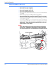
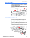
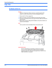
15. Remove the Exit Module (page 8-32).
Caution
The Drum Temperature Sensor harness is routed through the Exit
Module. Use care during removal to avoid damaging the sensor.
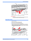
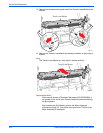
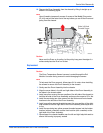
16. Remove the clevis pins securing the Transfix Load Arms to the chassis
and remove the Transfix Load Arms and the Stripper Carriage Assembly.
(See the figure on page 8-23.)
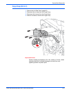
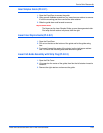
17. Remove 3 left-handed screws (8500/8550/8560) and washers from the
right side of the Drum Assembly. Note that one of the screws has no
washer. The 8400 uses 3 right-handed screws.
18. Remove 3 screws and washers from the left side of the Drum Assembly.
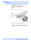
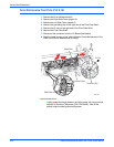
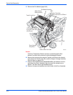
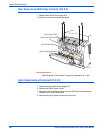
Transfix Load Arm
Media Release
Blade Assembly
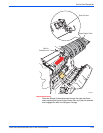
110 Connector (J250)
to Control Panel Cable
(Not Shown)
Drum Heater Cable
Drum Heater
Relay Board
Power Control Left Cable
Drum Encoder Cable
Exit Module Assembly
Drum Thermistor
Cable Connector to I/O Board
J850
s8500-091