


Phaser 8400/8500/8550/8560 Color Printer Service Manual 8-29
Service Parts Disassembly
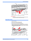
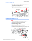
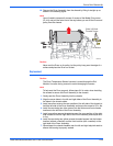
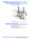
19. Remove the Drum Assembly from the chassis by lifting it straight up as
shown in the following figure.
N
o
t
e
You will need to temporarily remove 3 screws of the Media Drive motor
(PL 4.8) and pull the motor out of the way before you can lift the Drum and
pulley from the chassis.
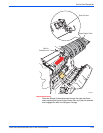
Caution
Never rest the Drum on its pulley. Let the pulley hang over the edge of a
surface and place the Drum on its feet.
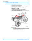
Replacement
Caution
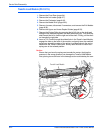
The Drum Temperature Sensor harness is routed through the Exit
Module. Use care during removal to avoid damaging the sensor.
N
o
t
e
To help seat the Drum properly, follow steps 2-6 in order, when installing
the screws to secure the Drum Assembly to the chassis.
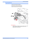
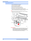
1. Gently seat the Drum Assembly into the chassis.
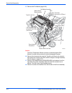
2. Align the screw holes in the left and right sides of the Drum Assembly to
the holes in the chassis sides.
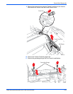
3. Install one silver screw at the rear position of the left-side of the chassis to
hold the left side of the Drum Assembly and torque the screw to 25 in. lbs.
4. Install the remaining two silver screws into the bottom and front chassis
locations to the left side of the Drum Assembly.
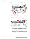
5. Install one yellow reverse-threaded screw at the rear position of the right-
side chassis to hold the right side of the Drum Assembly and torque to 25
in. lbs.
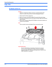
6. Install the remaining two yellow reverse-threaded screws into the bottom
location (without a washer) and the front location (with a washer) on the
right side of the Drum Assembly.
7. Spread apart the chassis handles near the left and right labyrinth seals to
ensure the bearing is properly sealed.
s8500-096
No Washer
Yellow Left-Hand
Threaded Screws