


Phaser 8400/8500/8550/8560 Color Printer Service Manual 8-15
Service Parts Disassembly
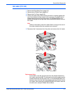
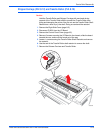
10. After completing the installation, print the Light Stripes Page and check
for jets in service mode. If necessary, use the Control Panel to reset the
jet substitution mode.
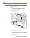
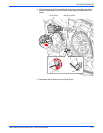
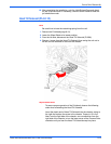
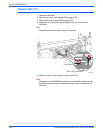
Head Tilt Solenoid (PL4.0.12)
N
o
t
e
Be careful not to lose the restraining spring from the unit.
1. Remove the Printhead (page 8-10).
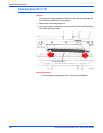
2. Lower the Wiper Blade to its lowest position.
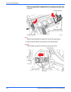
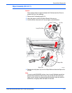
3. From the left side, disconnect the Head Tilt Solenoid (P/J208).
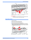
4. Remove 1 screw from the Head Tilt Solenoid, then swing the unit out to
the left until the solenoid is free from the chassis.
R
ep
l
acemen
t
N
o
t
e
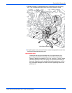
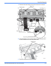
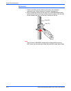
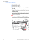
To ensure proper operation of the Printhead, observe the following
order when reinstalling the Head Tilt Solenoid.
Insert the plastic end of Head Tilt Solenoid into the chassis, swing to
the right and replace the screw in the chassis. Torque to 12 in-lbs.
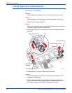
Next, from the right side of the chassis, use a screwdriver from the
right side of the chassis, to turn the lower screw of the Process Drive
clockwise until you hear the Head Tilt Solenoid snap into place.