


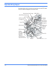

Phaser 8400/8500/8550/8560 Color Printer Service Manual 10-3
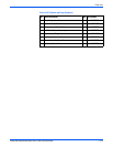
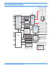
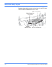
Main Wiring Diagram (Continued)
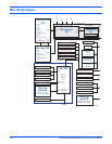
(Right
Side)
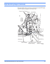
Power
Supply
ECB
AC
generates:
+/-50 V
+/-15 V unreg
+3.3 V
Power Control
ECB
Inkload ECB
Heaters (4)
Ink out opto
Ink low opto
Door open opto
Thermistor (4)
Pre-heat
ECB
Deskew entry
sense opto
Control Panel
ECB
generates:
+5 V
LCD Display
MPT ECB
Width sense var. resistor
Media present sense opto
I/O ECB
+50 V
+3.3 V
+/-50 V
+/-12 V unreg
+3.3 V
generates
+/- 12 V reg.
+5 V
Printer ambient
temperature
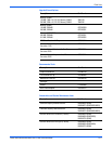
4
30 connector
4
2
4
7
3
3
10
10
3
3
5
10
10
5
5
3
3
7
42
2
2
2
2
3
2
42
16
2
14
14
34
6
8
2
2
2
X- axis motor
Y- axis motor
Main tray paper height opto
Main tray paper opto
Waste tray opto
Process home (optional)
Process motor
with encoder
Drum fan
Y axis pos encoder
ECB
I/O color coding
Black = input
Magenta = output
Red = temp
Printhead
AC Resv. heaters (2)
AC Jetstack heaters (2)
Drum Heater
Series/parallel heater
Paper preheater
Preheat temp therm
Preheat sense opto
Top door sense switch
Front door sense switch
Relay ECB
NOTE:
The numbers shown at the circuit board
perimeters are for the actual connectors.
Some have extra n.c. pins added to prevent
misplugging errors.
NOTE:
Thermal fuse for drum is located
on Pre-heated ECB
NOTE:
All items connected with RED
carry line voltage.
s8500-124
LINE
110/220
Auxilary
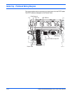
Connectors
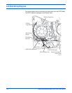
35
35
Black
Red
White
J620 J480
J400
J3AC
JDC1
J2AC
J4AC
J1AC
J0720
J2
J3
J1
J0670
J0660
J190
J110
J600
J860
J280
J820
J790
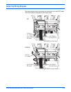
J390 (Left Side)
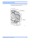
J870
J860
J680
J600 J610
J220
J110
J400
J250
J800 (Right Side)
J840 J910
J1
J2
Serial
Data
Bus