


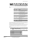


System Control Coprocessor
ARM DDI 0363E Copyright © 2009 ARM Limited. All rights reserved. 4-37
ID013010 Non-Confidential, Unrestricted Access
To use the System Control Register ARM recommends that you use a read-modify-write
technique. To access the System Control Register, read or write CP15 with:
MRC p15, 0, <Rd>, c1, c0, 0 ; Read System Control Register configuration data
MCR p15, 0, <Rd>, c1, c0, 0 ; Write System Control Register configuration data
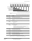
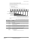
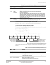
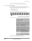
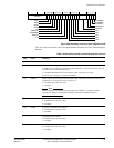
[19] DZ Divide by zero:
0 = do not generate an Undefined instruction exception
1 = generate an Undefined instruction exception.
The reset value of this bit is 0.
[18] Reserved SBO.
[17] BR MPU background region enable.
[16] Reserved SBO.
[15] Reserved SBZ.
[14] RR Round-robin bit, controls replacement strategy for instruction and data caches:
0 = random replacement strategy
1 = round-robin replacement strategy.
The reset value of this bit is 0. The processor always uses a random replacement strategy,
regardless of the state of this bit.
[13] V Determines the location of exception vectors:
0 = normal exception vectors selected, address range =
0x00000000
-
0x0000001C
1 = high exception vectors (HIVECS) selected, address range =
0xFFFF0000-0xFFFF001C
.
The primary input VINITHI defines the reset value.
[12] I Enables L1 instruction cache:
0 = instruction caching disabled. This is the reset value.
1 = instruction caching enabled.
If no instruction cache is implemented, then this bit is SBZ.
[11] Z Branch prediction bit.
The processor supports branch prediction. This bit is SBO. The Auxiliary Control Register can
control branch prediction, see Auxiliary Control Registers on page 4-38.
[10:7] Reserved SBZ.
[6:3] Reserved SBO.
[2] C Enables L1 data cache:
0 = data caching disabled. This is the reset value.
1 = data caching enabled.
If no data cache is implemented, then this bit is SBZ.
[1] A Enables strict alignment of data to detect alignment faults in data accesses:
0 = strict alignment fault checking disabled. This is the reset value.
1 = strict alignment fault checking enabled.
[0] M Enables the MPU:
0 = MPU disabled. This is the reset value.
1 = MPU enabled.
If no MPU is implemented, the MPU has zero regions, this bit is SBZ.
Table 4-23 System Control Register bit functions (continued)
Bits Field Function