


Debug
ARM DDI 0363E Copyright © 2009 ARM Limited. All rights reserved. 11-67
ID013010 Non-Confidential, Unrestricted Access
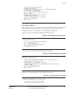
// Step 2. Write the address to R0.
WriteRegister(0, address);
// Step 3. Execute instruction LDC p14, c5, [R0] through the ITR.
ExecuteARMInstruction(0xED905E00);
// Step 4. Read the value from the DTR directly.
datum := ReadDCC();
// Step 5. Restore the corrupted register R0.
WriteRegister(0, saved_r0);
// Step 6. Check the DSCR for a sticky abort.
aborted := CheckForAborts();
return datum;
}
Fast register read/write
When multiple registers must be read in succession, you can optimize the process by placing the
DCC into stall mode and by writing the value 1 to the DCC access mode bits. For more
information, see CP14 c1, Debug Status and Control Register on page 11-14.
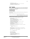
Example 11-22 shows the sequence to change the DTR access mode.
Example 11-22 Changing the DTR access mode
SetDTRAccessMode(int mode)
{
// Step 1. Write the mode value to DSCR[21:20].
dscr := ReadDebugRegister(34);
dscr := (dscr & ~(0x3<<20)) | (mode<<20);
WriteDebugRegister(34, dscr);
}
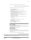
Example 11-23 shows the sequence to read registers in stall mode.
Example 11-23 Reading registers in stall mode
ReadRegisterStallMode(int Rd)
{
// Step 1. Write the opcode for MCR p14, 0, Rd, c5, c0 to the ITR.
// Write stalls until the ITR is ready.
WriteDebugRegister(33, 0xEE000E15 + (Rd<<12));
// Step 2. Read the register value through the DCC. Read stalls until
// DTRTX is ready
reg_val := ReadDebugRegister(32);
return reg_val;
}
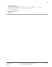
Example 11-24 shows the sequence to write registers in stall mode.
Example 11-24 Writing registers in stall mode
WriteRegisterInStallMode(int Rd, uint32 value)
{
// Step 1. Write the value to the DTRRX.
// Write stalls until the DTRRX is ready.