System Control Coprocessor
ARM DDI 0363E Copyright © 2009 ARM Limited. All rights reserved. 4-6
ID013010 Non-Confidential, Unrestricted Access
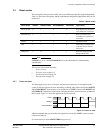
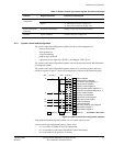
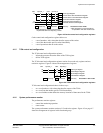
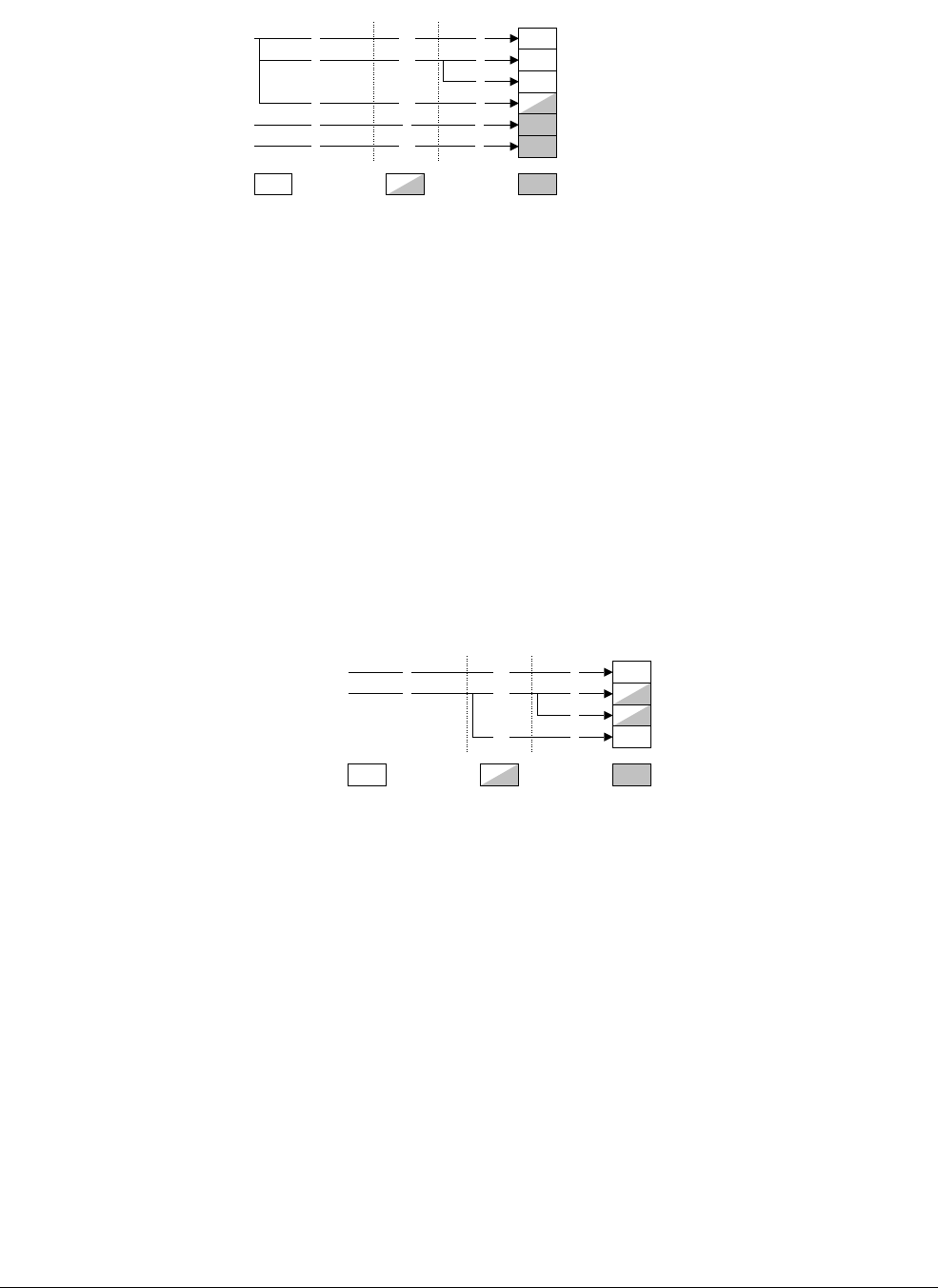
Figure 4-3 Cache control and configuration registers
Cache control and configuration registers behave as:
• a set of numbers, with values that describe aspects of the caches
• a set of bits that enable specific cache functionality
• a set of operations that act on the caches.
4.1.5 TCM control and configuration
The TCM control and configuration registers:
• inform the processor about the status of the TCM regions
• define TCM regions.
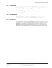
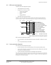
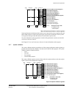
The TCM control and configuration registers consist of two read-only registers and two
read/write registers. Figure 4-4 shows the arrangement of registers.
Figure 4-4 TCM control and configuration registers
TCM control and configuration behaves in three ways:
• as a set of numbers, with values that describe aspects of the TCMs
• as a set of bits that enable specific TCM functionality
• as a set of addresses that define the memory locations of data stored in the TCMs.
4.1.6 System performance monitor
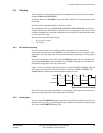
The performance monitor registers:
• control the monitoring operation
• count events.
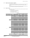
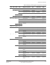
The system performance monitor consists of 12 read/write registers. Figure 4-5 on page 4-7
shows the arrangement of registers in this functional group.
Opcode_2CRmOpcode_1
1
c0 0 c0 Cache Type Register
CRn
c7
† Cache Operations Registers ‡
‡ See description of cache operations
for operations with User mode access
Invalidate all Data Cache Registerc15
0
0
0 c5
Write-only
Accessible in User mode
Read-only Read/write
Current Cache Size Identification Register
Current Cache Level Identification Register
Cache Size Selection Register
0
c01
1
0
2 c0
†
† See description of cache operations for
implemented CRm and Opcode_2 values
ATCM Region Register
1
c9
0
c0
2
0
0
c0
BTCM Region Register
TCM Type Register
CRn CRmOpcode_1 Opcode_2
TCM Selection Register
0
Write-only
Accessible in User mode
Read-only
Read/write
c1
c2


