


Level One Memory System
ARM DDI 0363E Copyright © 2009 ARM Limited. All rights reserved. 8-4
ID013010 Non-Confidential, Unrestricted Access
8.2 About the error detection and correction schemes
In silicon devices, stray radiation and other effects can cause the data stored in a RAM to be
corrupted. The TCMs and caches on Cortex-R4 can be configured to detect and correct errors
that can occur in the RAMs. Extra, redundant data is computed by the processor and stored in
the RAMs alongside the real data. When the processor reads data from the RAMs, it checks that
the redundant data is consistent with the real data and can either signal an error, or attempt to
correct the error.
A number of different error schemes are available, and are described in:
• Parity
• 64-bit ECC on page 8-5
• 32-bit ECC on page 8-5.
Each has different properties in terms of the number of errors that can be detected, and corrected,
and the amount of extra RAM required to store the redundant data. Because different logic is
required for each scheme, the scheme must be chosen in the build-configuration, although you
can enable or disable, or change the behavior of the error schemes using software-configuration.
This section describes the generic properties of each of the schemes. See Appendix B ECC
Schemes for more information about the advantages and disadvantages of each scheme to the
implementer. The details of operation of the error schemes for the caches are described in Cache
error detection and correction on page 8-20, and for the TCMs in TCM internal error detection
and correction on page 8-14.
The error schemes are each described in terms of their operation on a doubleword (64 bits) of
data, because this is the amount of data that the processor L1 memory system can transfer each
cycle. The tag and dirty RAMs associated with the caches are different sizes, but the principles
are the same. An error is considered to be a single bit of data that has been inverted relative to
its correct value.
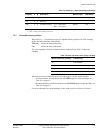
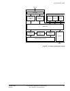
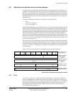
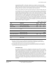
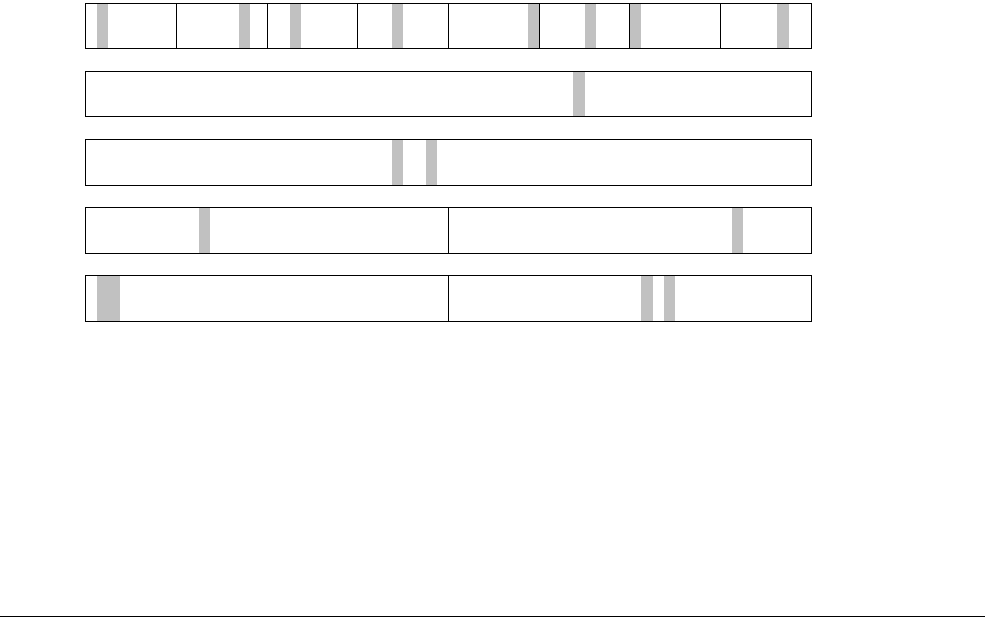
Figure 8-2 shows the error schemes. The shaded areas represent bits with errors.
Figure 8-2 Error detection and correction schemes
8.2.1 Parity
For each byte, a parity bit is computed and stored with that byte. This requires eight bits of
parity, or redundant data per doubleword. With a parity scheme, a single error in a byte or its
parity bit can be detected, but not corrected. This means that, provided they are all in different
bytes, eight errors can be detected per doubleword. However, if there are two errors in any
individual byte, this cannot be detected. Odd or even parity can be used, and this can be
pin-configured during integration.
Parity: one error per
byte detected
64-bit ECC: one error
per doubleword
corrected
64-bit ECC: two errors
per doubleword
detected
32-bit ECC: two errors
per word detected
32-bit ECC: one error
per word corrected