


Cycle Timings and Interlock Behavior
ARM DDI 0363E Copyright © 2009 ARM Limited. All rights reserved. 14-22
ID013010 Non-Confidential, Unrestricted Access
14.13.2 Load Multiples, where the PC is in the register list
The processor includes a 4-entry return stack that can predict procedure returns. Any
LDM
to the
PC that does not restore the SPSR to the CPSR, is predicted as a procedure return.
In all cases the base register,
<Rn>
, is a Very Early Reg.
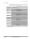
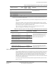
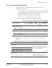
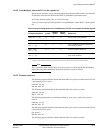
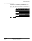
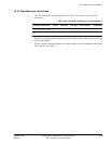
Table 14-18 shows the cycle timing behavior of Load Multiples, where the PC is in the register
list.
Note
The Cycle timing behavior that Table 14-18 shows also covers
PUSH
and
POP
instructions that
behave like store and load multiple instructions with base register writeback.
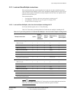
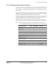
14.13.3 Example Interlocks
The following sequence that has an
LDM
instruction takes six cycles to execute, because R7 has
a result latency of five cycles:
LDMIA R0, {R1-R7}
ADD R10, R10, R7
The following sequence that has an
STM
instruction takes five cycles to execute:
STMIA R0, {R1-R7}
ADD R7, R10, R11
The following sequence has a result latency hidden by issue cycles. It takes five cycles to
execute.
LDMIA R0, {R1-R7}
ADD R10, R10, R3
The following sequence that has a
POP
instruction takes seven cycles to execute, because
R9
has
a result latency of six cycles:
POP {R1-R9}
ADD R10, R10, R9
The following sequence that has a
PUSH
instruction takes five cycles to execute:
Table 14-18 Cycle timing behavior of Load Multiples, with PC in the register list (64-bit aligned)
Example instruction Cycles
Memory
cycles
Result
latency
Comments
LDMIA <Rn>,{...,pc}
m
a
n
b
2,… Correct return stack prediction
LDMIA <Rn>,{...,pc}
m
a
+ 8 n
b
2,… Incorrect return stack prediction
LDMIA <cond>
<Rn>,{...,pc}
m
a
n
b
2,… Correct condition prediction and correct
return stack prediction
LDMIA <cond>
<Rn>,{...,pc}
m
a
+ 7 n
b
2,… Incorrect condition prediction
LDMIA <cond>
<Rn>,{...,pc}
m
a
+ 8 n
b
2,… Correct condition prediction and incorrect
return stack prediction
a. Where m is the number of cycles for this instruction if the PC were treated as a normal register.
b. Where n is the number of memory cycles for this instruction if the PC were treated as a normal register.