


System Control Coprocessor
ARM DDI 0363E Copyright © 2009 ARM Limited. All rights reserved. 4-73
ID013010 Non-Confidential, Unrestricted Access
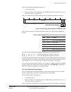
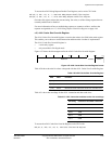
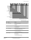
Figure 4-56 Build Options 2 Register format
Table 4-55 shows how the bit values correspond with the Build Options 2 Register.
31 25 24 23
22
21
19
17
16 14 13 12 11 7 6 3 026272830 29 1020 9 458
DUAL_CORE
DUAL_NCLK
NO_ICACHE
NO_DCACHE
ATCM_ES
BTCM_ES
NO_IE
NO_FPU
NO_MPU
MPU_REGIONS
BREAK_POINTS
WATCH_POINTS
NO_A_TCM_INF
NO_B0_TCM_INF
NO_B1_TCM_INF
TCMBUSPARITY
NO_SLAVE
ICACHE_ES
DCACHE_ES
N0_HARD_ERROR_CACHE
AXIBUSPARITY
2
RESERVED
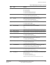
Table 4-55 Build Options 2 Register
Bits Field Function
[31]
DUAL_CORE
a
Indicates whether a second, redundant, copy of the processor logic and
checking logic was instantiated:
0 = single core
1 = dual core.
[30]
DUAL_NCLK
a
Indicates whether an inverted clock is used for the redundant core:
0 = inverted clock not used
1 = inverted clock used.
[29] NO_ICACHE Indicates whether the processor contains instruction cache:
0 = processor contains instruction cache
1 = processor does not contain instruction cache.
[28] NO_DCACHE Indicates whether the processor contains data cache:
0 = processor contains data cache
1 = processor does not contain data cache.
[27:26] ATCM_ES Indicates whether an error scheme is implemented on the ATCM interface:
00 = no error scheme
01 = 8-bit parity logic
10 = 32-bit error detection and correction
11 = 64-bit error detection and correction.