


Events and Performance Monitor
ARM DDI 0363E Copyright © 2009 ARM Limited. All rights reserved. 6-17
ID013010 Non-Confidential, Unrestricted Access
MRC p15, 0, <Rd>, c9, c14, 1 ; Read INTENS Register
MCR p15, 0, <Rd>, c9, c14, 1 ; Write INTENS Register
If this unit generates an interrupt, the processor asserts the pin nPMUIRQ. You can route this
pin to an external interrupt controller for prioritization and masking. This is the only mechanism
that signals this interrupt to the processor.
Note
ARM expects that the Performance Monitor interrupt request signal, nPMUIRQ, connects to a
system interrupt controller.
6.3.12 c9, Interrupt Enable Clear Register
The INTerrupt ENable Clear (INTENC) Register determines if any of the PMC Registers,
PMC0-PMC2 and CCNT, generate an interrupt request on overflow.
The INTENC Register is:
• a read/write register
• accessible in Privileged mode only.
Reading this register returns the current setting. Writing to this register can disable interrupt
requests. You can enable interrupt requests only by writing to the INTENS Register.
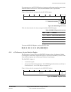
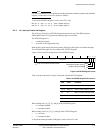
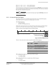
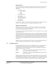
Figure 6-10 shows the bit arrangement for the INTENC Register.
Figure 6-10 INTENC Register format
Table 6-11 shows how the bit values correspond with the INTENC Register.
When reading bits [31], [2], [1], and [0] of the INTENC Register:
• 0 = interrupt disabled
• 1 = interrupt enabled.
When writing to bits [31], [2], [1], and [0] of the INTENC Register:
• 0 = no action
• 1 = interrupt disabled.
C
31 3210
Reserved
P2
P1
P0
Performance monitor counter
overflow interrupt disables
Cycle count overflow interrupt disable
Table 6-11 INTENC Register bit functions
Bits Field Function
[31] C CCNT overflow interrupt enable bit
[30:3] Reserved UNP on reads, SBZP on writes
[2] P2 Interrupt on PMC2 overflow when enabled
[1] P1 Interrupt on PMC1 overflow when enabled
[0] P0 Interrupt on PMC0 overflow when enabled