


Processor Signal Descriptions
ARM DDI 0363E Copyright © 2009 ARM Limited. All rights reserved. A-4
ID013010 Non-Confidential, Unrestricted Access
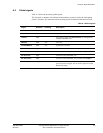
A.3 Configuration signals
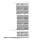
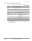
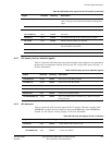
Table A-2 shows the processor configuration signals.
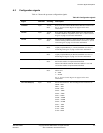
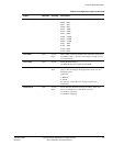
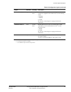
Table A-2 Configuration signals
Signal Direction Clocking Description
VINITHI Input Tie-off,
Reset
Reset V-bit value. When HIGH indicates HIVECS mode at reset.
See c1, System Control Register on page 4-35 for more
information.
CFGEE Input Tie-off,
Reset
Reset EE-bit value. When HIGH indicates the implementation
uses BE-8 mode for exceptions at reset. See c1, System Control
Register on page 4-35 for more information.
CFGIE Input Tie-off,
Reset
Instruction side endianness, reflected in the IE-bit. When HIGH
indicates that big endian instruction fetch is used. See c1, System
Control Register on page 4-35 for more information.
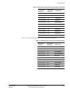
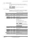
INITRAMA Input Tie-off,
Reset
Reset value of ATCM enable bit. When HIGH indicates
Tightly-Coupled Memory A, ATCM, enabled at reset. See c9,
ATCM Region Register on page 4-58 for more information.
INITRAMB Input Tie-off,
Reset
Reset value of BTCM bit. When HIGH indicates
Tightly-Coupled Memory B, BTCM, enabled at reset. See c9,
BTCM Region Register on page 4-57 for more information.
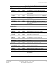
LOCZRAMA Input Tie-off,
Reset
When HIGH indicates ATCM initial base address is zero and
BTCM base address is implementation-defined.
When LOW indicates BTCM initial base address is zero and
ATCM base address is implementation-defined.
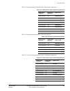
TEINIT Input Tie-off,
Reset
Reset TE-bit value. Determines exception handling state at reset.
When set to:
0 = ARM
1 = Thumb.
See c1, System Control Register on page 4-35 for more
information.
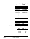
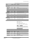
CFGATCMSZ[3:0] Input Tie-off Selects the ATCM size. The encodings for the TCM sizes are:
b0000 = 0KB
b0011 = 4KB
b0100 = 8KB
b0101 = 16KB
b0110 = 32KB
b0111 = 64KB
b1000 = 128KB
b1001 = 256KB
b1010 = 512KB
b1011 = 1MB
b1100 = 2MB
b1101 = 4MB
b1110 = 8MB.