


Standards Supported by These Cables
The cables comply with the following standards:
•
SFP mechanical standard SFF-843—see ftp://ftp.seagate.com/sff/SFF-8431.PDF.
•
Electrical interface standard SFF-8432—see ftp://ftp.seagate.com/sff/SFF-8432.PDF.
•
SFP+ Multi-Source Alliance (MSA) standards
Related Topics Optical Interface Support in EX3200 and EX4200 Switches•
• Optical Interface Support in EX4500 Switches
• Optical Interface Support in EX8200 Switches on page 60
• Installing a Transceiver in an EX Series Switch on page 163
• Removing a Transceiver from an EX Series Switch on page 222
Grounding Cable and Lug Specifications for EX8200 Switches
For installations that require a separate grounding conductor to the chassis, the switch
must be adequately grounded before power is connected to ensure proper operation
and to meet safety and electromagnetic interference (EMI) requirements. To ground an
EX8200 switch, connect a grounding cable to earth ground and then attach it to the
chassis grounding points.
CAUTION: Forinstallationsthatrequireaseparategroundingconductortothechassis,
use the protective earthing terminal on the EX8200 switch chassis to connect to earth
ground. Beforeswitchinstallation begins,a licensedelectricianmust attach acablelug
tothe grounding cables thatyou supply. See“ConnectingEarth Ground toan EX Series
Switch” on page 167. A cable with an incorrectly attached lug can damage the switch.
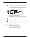
A pair of threaded inserts (PEM nuts) is provided on the right side towards the top rear
corner of the EX8208 chassis for connecting the switch to earth ground. The grounding
points fit UNC ¼-20 screws. The grounding points are spaced at 0.625 in. (15.86 mm).
Two pairs of threaded inserts (PEM nuts) are provided on the EX8216 chassis for
connecting the switch to earth ground. The first pair is located on the right side towards
the top rear corner of the chassis. The second pair is on the rear of chassis towards the
right bottom corner of the chassis. Both pairs of grounding points fit UNC ¼-20 screws.
The grounding points are spaced at 0.625 in. (15.86 mm).
NOTE: EX8216switcheshavetwoprotectiveearthingterminalsprovidedonthechassis.
Only one of theseprotective earthing terminals needs to be permanentlyconnected to
earthground.See ChassisPhysical Specifications of an EX8216 Switch forthe location
of the protective earthing terminals.
87Copyright©2010,Juniper Networks,Inc.
Chapter3:ComponentSpecifications