


The provided cable lugs in an EX8216 switch are sized for 2 AWG (33.6 mm
2
) power
source cables. The DC power source cables that you provide must be 2 AWG (33.6
mm
2
),minimum60°Cwire.Werecommendthatyouinstallheat-shrinktubinginsulation
around the power cables and lugs.
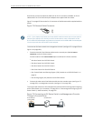
•
3/8 in. (9.5 mm) nut driver or socket wrench
•
Phillips (+) screwdriver, number 2
•
Multimeter
WARNING: Ensure that the power cords do not block access to switch components or
drape where people can trip on them.
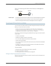
To connect DC power to an EX8200 switch:
1. Attach the electrostatic discharge (ESD) grounding strap to your bare wrist, and
connect the strap to the ESD point on the chassis.
2. Flip the Enable switch on the power supply faceplate to the Standby position.
NOTE: It might be necessaryto slide each power supply partially out of the chassis, in
order to easily connect the DC power source cables to the DC power input terminals.
See “Removing a DC Power Supply from an EX8200 Switch” on page 209.
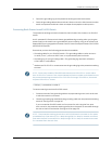
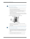
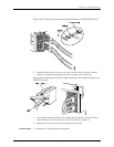
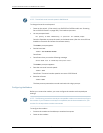
3. RemovetheplasticcablecoverfromtheDCpowerinputterminals,usingthenumber
2 Phillips (+) screwdriver to loosen the screw (see Figure 68 on page 177).
Figure 68: Removing the Plastic Cable Cover on a DC Power Supply in an
EX8200 Switch
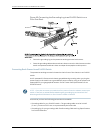
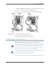
4. Remove the washers and nuts from each DC power input terminal, using the
3/8-in. (9.5 mm) nut driver or socket wrench to loosen the nuts. Leave the bolts
installed on the input terminals.
177Copyright©2010,Juniper Networks,Inc.
Chapter10:Connectingthe Switch