


2. Calculate the power budget (P
B
) by subtracting (P
R
) from (P
T
):
–15 dBm – (–28 dBm) = 13 dBm
Related Topics Calculating the EX8200 Switch Fiber-Optic Cable Power Margin on page 121•
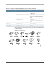
• Optical Interface Support in EX8200 Switches on page 60
• Understanding EX8200 Switch Fiber-Optic Cable Signal Loss, Attenuation, and
Dispersion on page 106
Calculating the EX8200 Switch Fiber-Optic Cable Power Margin
Calculate the link's power margin when planning fiber-optic cable layout and distances
to ensure that fiber-optic connections have sufficient signal power to overcome system
losses and still satisfy the minimum input requirements of the receiver for the required
performance level. The power margin (P
M
) is the amount of power available after
attenuation or link loss (LL) has been subtracted from the power budget (P
B
).
Whenyoucalculatethe power margin,youuse aworst-caseanalysis toprovideamargin
of error, even though all the parts of an actual system do not operate at worst-case
levels.Apowermargin(P
M
)greaterthanzeroindicatesthatthepowerbudgetissufficient
to operate the receiver and that it does not exceed the maximum receiver input power.
This means the link will work. A (P
M
) that is zero or negative indicates insufficient power
to operate the receiver.See the specification for your receiver to find the maximum
receiver input power.
Before you begin to calculate the power margin:
•
Calculate the power budget. See “Calculating the EX8200 Switch Fiber-Optic Cable
Power Budget” on page 120.
To calculate the worst-case estimate for the power margin (P
M
) for the link:
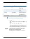
1. Determine the maximum value for link loss (LL) by adding estimated values for
applicable link-loss factors—for example, use the sample values for various factors
as provided in Table51 on page 121 (here, the link is 2 km long and multimode, and
the (P
B
) is 13 dBm):
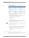
Table 51: Estimated Values for Factors Causing Link Loss
Sample (LL) Calculation ValuesEstimated Link-LossValueLink-Loss Factor
•
0.5dBm
•
0 dBm
•
Multimode—0.5 dBm
•
Singlemode—None
Higher-ordermode losses(HOL)
•
0 dBm
•
0 dBm
•
Multimode—None, if productof
bandwidth and distance is lessthan
500 MHz/km
•
Singlemode—None
Modal and chromatic dispersion
121Copyright©2010, JuniperNetworks, Inc.
Chapter7:PlanningPowerRequirements