


• Connecting and Configuring an EX Series Switch (CLI Procedure) on page 190
• Connecting and Configuring an EX Series Switch (J-Web Procedure) on page 192
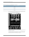
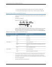
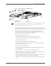
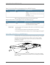
Chassis Status LEDs in an EX8200 Switch
The top front of the chassis of an EX8200 switch has three LEDs on the right side of the
LCD panel.
See Figure 6 on page 22.
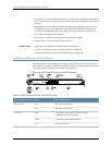
Figure 6: Chassis Status LEDs
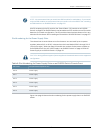
Table 8 on page 22 describes the chassis status LEDs in an EX8200 switch, their colors
and states, and the status they indicate. Youcan view the colors of the three LEDs
remotely through the CLI by issuing the operational mode command show chassislcd.
Table 8: Chassis Status LEDs in an EX8200 Switch
Stateand DescriptionColorLED Label (Description)
No alarm.UnlitALM (Alarm)
Major alarm.Red
Minor alarm.Yellow
Switchis poweredoff.UnlitSYS(System)
One or morecomponent failuresare generatingone or more
alarms.
Yellow
Switchis operatingnormally.Green
Switchis poweredoff.UnlitMST (Master)
Master RoutingEngine is operational.Green
A major alarm (red) indicates a critical error condition that requires immediate action.
A minor alarm (yellow) indicates a noncritical condition that requires monitoring or
maintenance. A minor alarm that is left unchecked might causeinterruption in service or
performance degradation.
All three LEDs can be lit simultaneously.
Copyright ©2010,Juniper Networks,Inc.22
CompleteHardwareGuide forEX8208 EthernetSwitches