


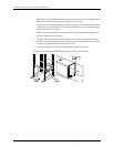
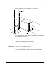

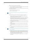
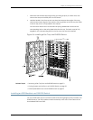

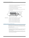

Figure 53: Installing a DC Power Supply in an EX8200 Switch
Related Topics Removing a DC Power Supply from an EX8200 Switch on page 209•
• DC Power Supply in an EX8200 Switch on page 48
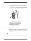
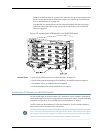
Installing a Fan Tray in an EX8208 Switch
AnEX8208 switchhas asingle,field-replaceable fan tray.Thefantray isa hot-insertable
and hot-removable field-replaceable unit (FRU); you can remove and replace the fan
tray while the switch is running without turning off power to the switch or disrupting
switching functions.
Thefan tray installs vertically on the left side on the front of the chassis.A handle on the
front faceplate facilitates handling of the fan tray.There is a spring-loaded latch on the
base of the fan tray that is used to latch the fan tray into the chassis.
Before you begin to install a fan tray:
•
Ensure you understand how to prevent ESD damage. See “Prevention of Electrostatic
Discharge Damage on EX Series Switches” on page 292.
Ensure that you have the following parts and tools available to install a fan tray in an
EX8208 switch:
•
Electrostatic discharge (ESD) grounding strap
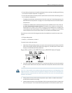
CAUTION: The fantray can be removed and replaced while the switch is operating.
However,the fan tray must be replaced within 2 minutes of removing the fan trayto
prevent the chassis from overheating.
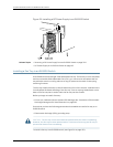
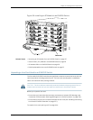
To install a fan tray in an EX8208 switch (see Figure 54 on page 155):
Copyright ©2010,Juniper Networks,Inc.154
CompleteHardwareGuide forEX8208 EthernetSwitches