


•
16 mounting screws appropriate for your rack to attach the four mounting bracket
pieces to the rack
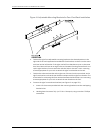
When you install the adjustable mounting brackets, the “arms” of the brackets overlap.
The overlap area adjusts the total bracket length to fit three standard rack sizes: 23.62
in. (600 mm), 30 in. (762 mm), and 31.5 in. (800 mm).
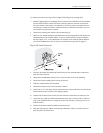
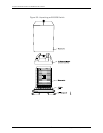
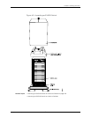
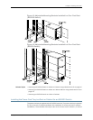
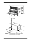
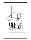
Toinstallthe mountingbracketsinafour-postrack(see Figure42 onpage135andFigure
43 on page 135):
1. Remove the adjustable mounting brackets from the accessory box.
2. Decide where to position the switch in the rack. If the rack is empty, position the
switch in the lowest possible location. See “Rack Requirements for an EX8208
Switch”onpage97,RackRequirementsforanEX8216Switch,“CabinetRequirements
and Specifications for an EX8208 Switch” on page 100, and Cabinet Requirements
and Specifications for an EX8216 Switch.
3. Position the left front adjustable mounting bracketat the desired position in the left
side of the rack and line up its front screw holes with the holes in the rack. Use 4
mounting screws appropriate for your rack to attach the left front bracket to the
rack.
4. Position one of the rear brackets at the left rear of the rack on the same level as the
left front bracket, so that the rear bracket overlaps with the left front bracket. The
screwholesforconnectingthefrontandrearbracketsshouldoverlap.Use4mounting
screws appropriate for your rack to attach the rear bracket to the rack.
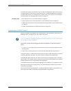
5. Connect left front and rear brackets (see Figure 41 on page 134):
a. Insert6 of the screwsprovidedwith the mounting bracketsinto the overlapping
bracket holes.
b. Hand tighten the screws fully (to 12–16 in.-lb torque) using a number 2 Phillips
screwdriver.
133Copyright©2010, JuniperNetworks, Inc.
Chapter8:Installing theSwitch