


•
Phillips (+) screwdriver, number 2
•
3/8 in. (9.5 mm) nut driver or socket wrench
•
Replacement power supply or cover panel for the power supply slot
CAUTION: Do not leave the powersupply slot empty for a long time while the switch
is operational. Either replace the powersupply unit promptly or install a cover panel
over the empty slot.
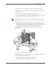
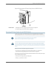
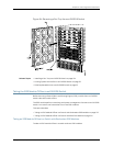
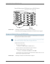
To remove a DC power supply from an EX8200 switch (see Figure 83 on page 211):
1. Attach the electrostatic discharge (ESD) grounding strap to your bare wrist, and
connect the strap to the ESD point on the chassis.
2. Make sure that the voltage across the DC power source cables leads is 0 V and that
thereis no chancethat the cables might become active during the removal process.
3. Flipthe Enable switch on the power supply to the Standby position.
4. Unscrew the screw counterclockwise using the Phillips (+) screwdriver, number 2,
on each of the plastic cable covers that shield the input terminal studs.
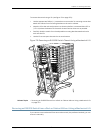
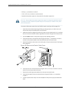
5. Remove the plastic cable covers from both pairs of input terminal studs. See Figure
82 on page 210.
Figure 82: Remove the Plastic Cable Cover
6. Unscrew the nuts counterclockwise using the 3/8 in. (9.5 mm) nut driver or socket
wrench from the input terminal studs.
7. Remove the cable lugs and washers from the input terminal studs.
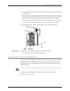
8. Unscrew the captive screw counterclockwise using the Phillips (+) screwdriver,
number 1.
9. Pull the captive screw away from the faceplate of the power supply to release the
latch.
Copyright ©2010,Juniper Networks,Inc.210
CompleteHardwareGuide forEX8208 EthernetSwitches