


•
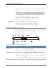
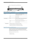
Console port—Connects the SRE moduleto a systemconsolethrough a cable with an
RJ-45 connector.See “Connecting an EX Series Switch to a Management Console” on
page 181.
•
Management port—Connects the SRE module through an Ethernet connection to a
management LAN (or any other device that plugs into an Ethernet connection) for
out-of-band management. See “Connecting an EX Series Switch to a Network for
Out-of-Band Management” on page 187.
•
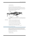
Ejector levers—Used for installing and removing the SRE module.
•
Captive screws—Secure the SRE module in place.
Related Topics Installing an SRE Module in an EX8208 Switch on page 155•
• Removing an SRE Module from an EX8208 Switch on page 215
• Takingthe SRE Module Offline in an EX8208 Switch on page 213
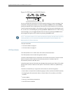
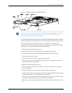
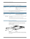
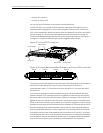
SRE Module LEDs in an EX8208 Switch
Each Switch Fabric and Routing Engine (SRE) module has four LEDs on the left side of
the module’s front panel. See Figure 8 on page 26. Table 10 on page 26 describes these
LEDs, their colors and states, and the status they indicate.
Figure 8: SRE Module LEDs in an EX8208 Switch
Table 10: SRE Module LEDs of an EX8208 Switch
Stateand DescriptionColorLED Label (Description)
SRE moduleis powered on.GreenON (PowerOn)
SRE moduleis powered off.Unlit
•
On steadily—SRE moduleis operatingnormally.
•
Blinking—SREmoduleis booting.
GreenST (Status)
•
On steadily—SRE modulehasfailed.Yellow
SRE moduleis offline.Unlit
Copyright ©2010,Juniper Networks,Inc.26
CompleteHardwareGuide forEX8208 EthernetSwitches