


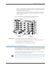


NOTE: Werecommend that you install two SRE modules for redundancy. If you install
only one SRE module, we recommend that you install it in the slot SRE0.
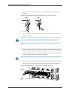
CAUTION: Do not lift the SRE module by holding the ejector levers. The levers cannot
support the weight of the module. Lifting the modules by the levers might bend the
levers, and the bent levers will prevent the SRE module from being properly seated in
the chassis.
Before you begin installing an SRE module in an EX8208 switch:
•
Ensure you understand how to prevent ESD damage. See “Prevention of Electrostatic
Discharge Damage on EX Series Switches” on page 292.
Ensure that you have the following parts and tools available to install an SRE module:
•
Electrostatic discharge (ESD) grounding strap
•
Phillips (+) screwdriver, number 2
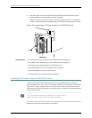
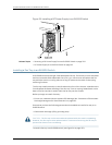
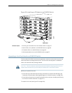
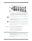
To install an SRE module in an EX8208 switch (see Figure 55 on page 157):
1. Attach the electrostatic discharge (ESD) grounding strap to your bare wrist and
connect the strap to one of the ESD points on the chassis.
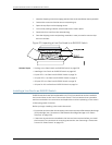
2. Taking care not to touch the leads, pins, or solder connections, pull the SRE module
out from the bag.
3. Pull both the ejector levers outward, away from the faceplate of the SRE module,
until they go no further.
4. If the slot hasa coverpanel on it, unscrewthe two screws on either side of the cover
panel counterclockwise using the Phillips (+) screwdriver, number 2. Remove the
cover panel. Save the cover panel for later use.
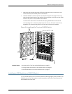
5. Carefully align the sides of the SRE module with the guides inside the chassis.
6. Ensuring that the SRE module is correctly aligned, carefully slide it into the chassis
until you feel resistance.
7. PushboththeejectorleverstowardsthefaceplateoftheSREmoduleuntilthelevers
are flush against the faceplate and are fully engaged.
8. Tighten the screws, one on each side of the SRE module, by turning them clockwise
using the Phillips (+) screwdriver, number 2. Ensure that the SRE module is fully
seated in the chassis. It must be fully seated in order for it to be powered up.
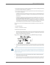
9. VerifythattheSREmoduleisinstalledcorrectlyandfunctioningnormallybychecking
the LEDs on the faceplate of the SRE module. The ON LED and ST LED should be lit
steady green a few minutes after the SRE module is installed.
If the ON LED is unlit, verify that there are enough power supplies installed. See
“CalculatingPower Requirementsforan EX8208Switch” onpage114. If morepower
supplies are needed, install additional power supplies. See “Installing an AC Power
Copyright ©2010,Juniper Networks,Inc.156
CompleteHardwareGuide forEX8208 EthernetSwitches