


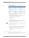
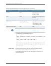


Table 51: Estimated Values for Factors Causing Link Loss (continued)
Sample (LL) Calculation ValuesEstimated Link-LossValueLink-Loss Factor
Thisexample assumes5 connectors.
Lossfor5 connectors:
5(0.5 dBm) = 2.5 dBm
0.5dBmConnector
Thisexampleassumes2splices.Lossfor
twosplices:
2(0.5 dBm) = 1dBm
0.5dBmSplice
Thisexample assumesthe link is 2 km
long.Fiber attenuationfor2 km:
•
2 km(1.0dBm/km) = 2 dBm
•
2 km( 0.5dBm/km) = 1 dBm
•
Multimode—1 dBm/km
•
Singlemode—0.5dBm/km
Fiber attenuation
1 dBm1dBmClockRecovery Module(CRM)
NOTE: For information about the actualamount of signal loss caused by equipment
and other factors, see your vendor documentation for that equipment.
2. Calculate the (P
M
) by subtracting (LL) from (P
B
):
P
B
– LL = P
M
13 dBm – 0.5 dBm [HOL] – 5 (0.5 dBm) – 2 (0.5 dBm) – 2 km (1.0 dBm/km) – 1 dB
[CRM] = P
M
13 dBm – 0.5 dBm – 2.5 dBm – 1 dBm – 2 dBm – 1 dBm = P
M
P
M
= 6 dBm
Thecalculatedpowermarginisgreaterthanzero,indicatingthatthelinkhassufficient
powerfortransmission.Also,thepowermarginvaluedoesnotexceedthemaximum
receiverinputpower.Refer tothespecificationfor yourreceivertofindthe maximum
receiver input power.
Related Topics • Calculating the EX8200 Switch Fiber-Optic Cable Power Budget on page 120
• Optical Interface Support in EX8200 Switches on page 60
• Understanding EX8200 Switch Fiber-Optic Cable Signal Loss, Attenuation, and
Dispersion on page 106
Copyright ©2010,Juniper Networks,Inc.122
CompleteHardwareGuide forEX8208 EthernetSwitches