


Ensure that you have an Ethernet cable with an RJ-45 connector available. An RJ-45
cable and an RJ-45 to DB-9 serial port adapter are supplied with the switch.
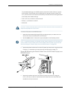
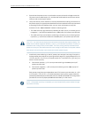
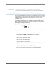
Figure72on page 182showstheRJ-45connector ofthe Ethernetcable suppliedwith the
switch.
Figure 72: Ethernet Cable Connector
NOTE: If your laptop or PC does not have a DB-9 male connector pin and you want to
connect yourlaptop or PC directly to an EX Series switch, use a combination of the
RJ-45toDB-9femaleadaptersuppliedwiththeswitchandaUSBtoDB-9maleadapter.
You must provide the USB to DB-9 male adapter.
ToconnectanEXSeriesswitchtoamanagementconsole(seeFigure73onpage182and
Figure 74 on page 183):
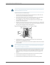
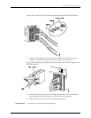
1. Connect one end of the Ethernet cable into the console port (labeled CON or
CONSOLE) on the EX Series switch.
For the location of the CON/CONSOLE port on different EX Series switches:
•
See Rear Panel of an EX2200 Switch.
•
See Rear Panel of an EX3200 Switch.
•
See Rear Panel of an EX4200 Switch.
•
See Front Panel of an EX4500 Switch.
•
See “Switch Fabric and Routing Engine (SRE) Module in an EX8208 Switch” on
page 24.
•
See Routing Engine (RE) Module in an EX8216 Switch.
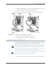
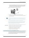
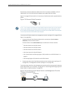
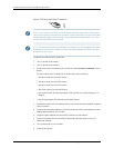
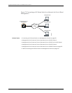
2. Connect the other end of the Ethernet cable into the console server (see Figure 73
on page 182) or management console (see Figure 74 on page 183).
To configure theswitchfromthe managementconsole,see“Connectingand Configuring
an EX Series Switch(CLI Procedure)”on page 190 or “Connecting and Configuringan EX
Series Switch (J-Web Procedure)” on page 192.
Figure 73: Connecting an EX Series Switch to a Management Console
Through a Console Server
g020547
Console server
PC
ToConsole port
(on the switch)
Copyright ©2010,Juniper Networks,Inc.182
CompleteHardwareGuide forEX8208 EthernetSwitches