


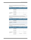


Table 28: DC Power Supply LEDs in EX8200 Switches (continued)
DescriptionStateLED
Indicatesone of the following:
•
Powersupplyis disconnected from DC power feed.
•
DC power input voltageis not within normal
operating range (-40 VDC through-72 VDC).
•
No DC power input.
UnlitB IN OK
•
DC power input voltageis within the normal
operating range (–40 VDC through–72 VDC).
Green
•
DC input is presenton the terminalsbut either the
fuse is trippedor the ORing diode is open.
Yellow
•
DC power input voltageis reversedin polarity.
NOTE: The DC powersupplyis protectedagainst
reversepolarityinput for both DC input feeds.
Red
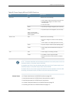
Indicatesone of the following:
•
DC output voltage is not within normal operating
range.
•
Powersupplyis not supplying DC power correctly.
UnlitOUTOK
•
DC power output is within normal operating range.Green
•
Powersupplyhas been disabled internally bythe
system.
Yellow
•
Powersupplyis functioning normally.UnlitFAIL
•
On steadily—Power supplyhasfailed.
•
Blinking—Demandfor output power exceedsthe
supply.
Yellow
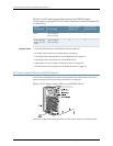
NOTE: Ifthe IN OK LED and the OUTOK LED are unlit, the power cordsarenot installed
properly or the power supply has failed.
IftheINOK LEDislitgreenandtheOUTOKLEDisunlit,thepowersupplyisnotinstalled
properly or the power supply has an internal failure.
If the FAIL LED is lit, the powersupply has failed and must be replaced. If the FAIL LED
is blinking, add a power supply to balance the power demand and supply.
Related Topics DC Power Specifications for EX8200 Switches on page 110•
• Power Requirements for EX8216 Switch Components
• Connecting DC Power to an EX8200 Switch on page 175
Copyright ©2010,Juniper Networks,Inc.52
CompleteHardwareGuide forEX8208 EthernetSwitches