


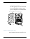
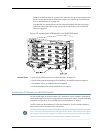

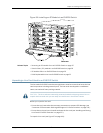
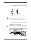
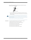
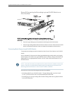

Figure 61: Installing a Line Card with a 4-in. Ejector Lever
9. Tightenthe captive screws on thefaceplateof the line card byusing the screwdriver.
10. Verify that the ON LED starts blinking in green. When the ON LED is lit steadily, the
line card is ready for use. If the ON LED does not blink or is not lit steadily, see
“Troubleshooting Line Card Installation on EX8200 Switches” on page 237.
CAUTION: After the ON LED is lit steadily, wait forat least 30 seconds before installing
another line card or removing a line card.
You can verify that the line card is functioning correctly by issuing the show chassisfpc
and show chassis fpc pic-status commands.
NOTE: If you have a Juniper J-Careservice contract, register any addition, change, or
upgradeof hardware components at
https://www.juniper.net/customers/csc/management/updateinstallbase.jsp. Failure to
do so can result in significant delays if you need replacement parts. This note applies
if you change the type of line card.It does not apply if you replace these components
with the same type of component.
Related Topics Removing a Line Card from an EX8200 Switch on page 218•
• 8-port SFP+ Line Card in an EX8200 Switch on page 30
• 40-port SFP+ Line Card in an EX8200 Switch on page 31
• 48-port SFP Line Card in an EX8200 Switch on page 33
• 48-port RJ-45 Line Card in an EX8200 Switch on page 34
Installing a Transceiver in an EX Series Switch
The transceivers for EX Series switches are hot-removable and hot-insertable
field-replaceable units (FRUs): Youcan remove and replace them without powering off
the switch or disrupting switch functions.
Use only optical transceivers and optical connectors purchased from Juniper Networks
for your EX Series switch.
163Copyright©2010,Juniper Networks,Inc.
Chapter9:Installing SwitchComponents