


• Installing and Removing EX8208 Switch Hardware Components on page 149
Understanding EX8208 Switch Component and Functionality Redundancy
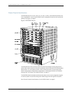
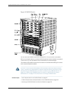
The Juniper Networks EX8208 Ethernet Switch is available as a fully redundant system.
A redundant EX8208 switch configuration is designed so that no single point of failure
can cause the entire switch to fail. See “EX8208 Switch Configurations” on page 6.
This topic describes:
•
Hardware Components That Provide Redundancy on page 11
•
Routing Engine and Control Redundancy on page 12
•
Switch Fabric Redundancy on page 12
Hardware Components That Provide Redundancy
The following hardware components provide redundancy to an EX8208 switch:
•
SRE modules—An EX8208 switch can have either one Switch Fabric and Routing
Engine (SRE) module or two SRE modules. If two SRE modulesare installed, one SRE
module functions as the master and the other functions as the backup. If the master
SRE module fails or is removed the backup module takes over as the master SRE
module.
WhentheSREmodulesareconfiguredforgracefulswitchover,thebackupSREmodule
automatically synchronizes its configuration and state with those of the master SRE
module.AnyupdatetothemasterSREmoduleisreplicatedonthebackupSREmodule.
If the backup module assumes mastership, packet forwarding continues through the
switch.
•
Power supplies—You can install up to six AC or six DC power supplies in an EX8208
switch. Eachpowersupplyconnectsto thebackplaneof the chassis,whichdistributes
the output power produced by the power supplies to different switch components.
(See“BackplaneinanEX8208Switch”onpage55.)Eachpowersupplyprovidespower
to all the components in the switch.
AnN+1powerconfigurationisrequiredforJuniperNetworksEX8200EthernetSwitches.
In an N+1 power configuration, if one power supply fails or is removed, the remaining
power supplies continue to supply power for the entire system without interruption. If
dual power feed redundancy is required, the required power configuration is N+N. The
DC power supplies provide independent A and B power feeds so that dual power
redundancy is available even in an N+1 power configuration. See “AC Power Supply in
anEX8200Switch”onpage40and“DCPowerSupplyinanEX8200Switch”onpage48.
•
Coolingsystem—The cooling system in an EX8200 switch consistsof a single fan tray.
The fan tray contains 12 fans. Under normal operating conditions, the fans in the fan
tray run at less than full speed.
The fans are controlled by two fan tray controllers. The fans are numbered 1 through
12. Fans 1 through 6 are controlled by the first fan tray controller. Fans 7 through 12 are
controlled by the second fan tray controller.If one fan tray controller fails, the other
11Copyright©2010, JuniperNetworks, Inc.
Chapter1:EX8208 SwitchOverview