


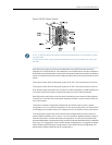
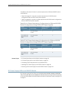
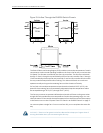

Figure 31: Airflow Through the EX8208 Switch Chassis
TheSwitchFabricandRoutingEngine(SRE)modulemonitorsthetemperatureofswitch
components.Under normal operatingconditions,the fans in the fan tray run atlessthan
full speed. The fans are controlled by two fan tray controllers. The fans are numbered 1
through 12. Fans 1 through 6 are controlled by the first fan tray controller. Fans 7 through
12arecontrolledbythe secondfan traycontroller.If onefantray controllerfails,the other
fan tray controller keeps half the fans working. This allows the switch to continue to
operate normally as long as the remaining fans cool the chassis sufficiently.
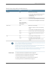
If a fan fails or the ambient temperature rises above the threshold 113°F (45°C), the
speed of the remaining fans is automatically adjusted to keep the temperature within
the acceptable range, 32°F (0°C) through 104°F (40°C).
The fan tray continues to operate indefinitely and provide sufficient cooling even when
a single fan fails provided the room temperature is within the operating range. You can
checkthestatusoffansandthechassistemperaturefromtheEnvironmentStatusoption
in the Status menu on the LCD panel. See “LCD Panel in an EX8200 Switch” on page 17.
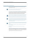
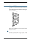
You cannot replace a single fan. If one or more fans fail, you must replace the entire fan
tray.
WARNING: There is no fan guard on the fans. Be careful to keep your fingers clearof
moving fan blades when you are removing the fan tray.
Copyright ©2010,Juniper Networks,Inc.54
CompleteHardwareGuide forEX8208 EthernetSwitches