


Removing an SRE Module from an EX8208 Switch
You must removethe Switch FabricandRoutingEngine (SRE) modulefromthe EX8208
switch chassis if you need to replace the module or if you need to remove switch
components before moving the chassis without using a mechanical lift.
CAUTION: Do not lift the SRE module by holding the ejector levers. The levers cannot
support the weight of the module. Lifting the moduleby the levers might bend the
levers.BentleverswillpreventtheSREmodulefrombeingproperlyseatedinthechassis.
Before you begin to remove an SRE module:
•
Ensure you understand how to prevent ESD damage. See “Prevention of Electrostatic
Discharge Damage on EX Series Switches” on page 292.
Ensure that you have the following parts and tools available to remove an SRE module:
•
Electrostatic discharge (ESD) grounding strap
•
Phillips (+) screwdriver, number 2
•
Antistatic bag or antistatic mat
•
Replacement SRE module or cover panel for the SRE module slot
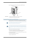
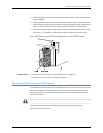
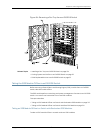
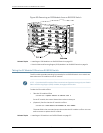
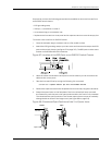
To remove an SRE module from an EX8208 switch (see Figure 85 on page 216):
1. Take the SRE module offline. See “Taking the SRE Module Offline in an EX8208
Switch” on page 213.
2. Attachtheantistaticdischarge(ESD)groundingstraptoyourbarewristandconnect
the strap to one of the ESD points on the chassis.
3. Place the antistatic bag or antistatic mat on a flat, stable surface.
4. LoosenthescrewsoneachsideoftheSREmodulebyturningthemcounterclockwise
using the screwdriver until they are completely unseated.
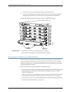
5. Pull both the ejector levers outwards, away from the faceplate of the SRE module,
untiltheygonofurther.ThisactioncausestheSREmoduletoslideoutofthechassis
slightly.
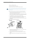
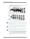
6. Grasp the ejector levers and pull the SRE module out to about halfway.
7. Taking care not to touch the leads, pins, or solder connections, place one hand
underneath the SRE module to support it and slide it completely out of the chassis.
8. Place the SRE module in the antistatic bag or on the antistatic mat.
9. If you are not replacing the SRE module, place the cover panel over the empty slot,
insert the screws through the holes on each side of the cover panel, and tighten the
screws with the screwdriver.
215Copyright©2010, JuniperNetworks, Inc.
Chapter13: RemovingSwitchComponents