


DEFINITY Enterprise Communications Server Release 8.2
Upgrades and Additions for R8r
555-233-115
Issue 1
April 2000
Upgrading R5si/R6si to R8r EPN and Adding Memory
3-38Release 5/6si to Release 8r
3
Switch-Connected Port Networks
For 1 to 15 Standard Reliability EPNs.
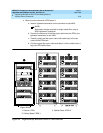
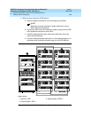
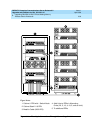
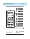
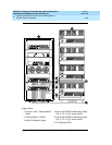
1. Behind the PPN cabinet. See Figure 3-14
:
a. Install a lightwave transceiver on cable connector at slot 1E02.
b. Install a lightwave transceiver on cable connector at slot 1B02.
c. Connect 1 end of the metallic intercarrier cable to the lightwave
transceiver at slot 1E02.
d. Route the intercarrier cable from the lightwave transceiver to the
cabinet cable tray and upward to carrier ‘‘B."
e. Connect the other end of the intercarrier cable to the lightwave
transceiver at slot 1B02.
f. Attach the intercarrier cable (with cable ties) to the wall of the cable
tray at the built-in cable tie positions.
2. Behind switch node carrier E of PPN cabinet 1. See
Figure 3-14
:
a. For each EPN, install 1 lightwave transceiver on a cable connector
with the following order of slots: 1E20, 1E03, 1E19, 1E04, 1E18,
1E05, and so forth.
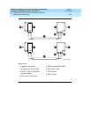
b. Connect 1 end of each fiber optic cable to each lightwave
transceiver, just installed.
c. Carefully attach the fiber optic cables (with cable ties) to the wall of
the cable tray at the built-in cable tie positions.
3. Behind control cabinet A of each single-carrier EPN:
a. Install a lightwave transceiver on cable connector at slot A01.
b. Connect the other end of the fiber optic cable to the lightwave
transceiver, just installed, at slot A01.
c. Carefully attach the fiber optic cable (with cable ties) to the rear
covers of the EPN stack.
d. Coil up the surplus length of fiber optic cable, and place the coil
either in the cable manager or on the bottom shelf (holding the
power supply) of the PPN cabinet.