


DEFINITY Enterprise Communications Server Release 8.2
Upgrades and Additions for R8r
555-233-115
Issue 1
April 2000
Multicarrier G2 Universal Module to R8r EPN
5-23Standard Reliability
5
Unpack and Inspect Expansion Control Carrier
1. Inspect the new J58890AF Expansion Control Carrier for any damage.
Also verify that the backplane pins are not bent.
2. Place the expansion control carrier on the floor so that the rear of the
carrier faces up.
3. Install the CFY1 current limiter (CURL) on the “A” carrier to the pin-field
block labeled “CURL” Install the CURL with the components on the left.
4. At the rear connector panel, determine which connectors will have a cable
attached, and install a 4B cable retainer on each of these connectors.
Install New Expansion Control Carrier A
1. Install the carrier in position “A” by aligning the plastic alignment tips on
the top rear of the carrier with the screw holes in the cabinet. These
alignment tips support the carrier while installing the screws. Ensure that
the power cords are properly placed in the slots at the sides of the carrier.
2. Fasten the carrier into position with 4 self-tapping screws saved from the
removal of the old carrier.
NOTE:
Carefully realign the threads on the self-tapping screws by turning
them counterclockwise 1 turn before tightening them to avoid
stripping the threads out of the framework.
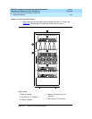
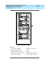
3. Connect the “P2” and “P1” cables to the “A” carrier. See
Figure 5-3
. Snap
the connector lock into place to ensure the connection is properly made.
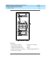
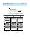
4. Connect the 8 ground straps from the “C” carrier to the new “A” carrier.
See
Figure 5-2
.
5. Connect the 8 ground straps from the “D” carrier to the new “A” carrier.
6. For AC-powered systems, install the 2 new ground straps. One strap
connects ground point “1” to the “A” carrier frame (right side), and the
other connects ground point “8” to the “A” carrier frame (left side).
NOTE:
DC-powered systems do not use these carrier ground straps.
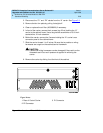
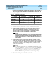
7. Connect the remaining end of the TDM/LAN cable (between the “A” and
“D” carriers) to the pin-field block marked “TDM” on the right side of the
“A” carrier. See
Figure 5-4
and
Table 5-7
.
8. Connect the remaining end of the TDM/LAN cable (between the “A” and
“C” carriers) to the pin-field block marked “TDM” on the left side of the “A”
carrier.