


DEFINITY Enterprise Communications Server Release 8.2
Upgrades and Additions for R8r
555-233-115
Issue 1
April 2000
Multicarrier G2 Universal Module to R8r EPN
5-91Critical Reliability
5
Interconnect Port Networks — Critical Reliability
Fiber optic cabling terminated to 9823A lightwave transceivers can interconnect
PNs up to 4,900 feet (1493 m) apart. Fiber optic cabling terminated to 9823B
lightwave transceivers can interconnect PNs up to 25,000 feet (7620 m) apart.
NOTE:
These distance limits are approximate measurements of the
actual
fiber
right-of-way (not of the shortest linear distance) between the 2 endpoints.
NOTE:
It is important to label every cable that you install.
NOTE:
Keep track of which fiber attaches to which connector on each lightwave
transceiver. This section provides figures offering the suggested way of
making these connections.
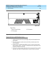
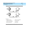
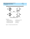
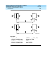
The connectors on the lightwave transceivers are labeled either “TX”
(transmit) or “RX” (receive), while the fibers attached to each connector are
numbered either “1” or “2.” A viable fiber connection is only made when
both fibers in each cable (“1” and “2”) route from the “TX” connector of a
port network to the “RX” connector of its adjacent port network. For an
example, refer to
Figure 5-29 on page 5-96
.
NOTE:
When finished, refer to Appendix A, ‘‘Fiber Link Administration’’ to
administer the fiber links.
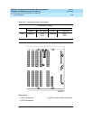
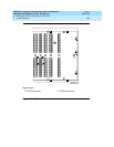
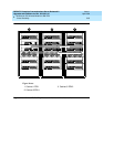
Collocated Port Networks
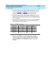
For a critical reliability system with 1 collocated EPN, use 2 fiber optic cables and
4 lightwave transceivers to directly connect the networks. For a critical reliability
system with 2 collocated EPNs, use 6 fiber optic cables and 12 lightwave
transceivers to directly connect the networks.
NOTE:
Based on floor-plan considerations, the length of these cables may vary.
Twenty-foot (6.1 m) cables are normally adequate for a Release 8 with 2
port networks.
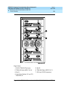
For collocated cabinets, the fiber optic cables should be routed directly from the
PPN to the EPN cabinet. If a “DEFINITY style” PPN cabinet is collocated with
another “DEFINITY style” EPN cabinet, route the cables
up
the cable tray and out
the top of the PPN cabinet. The cables are then run to the other cabinet, through
the top of the cabinet, and down the cable tray to the desired carrier level.
If a “DEFINITY style” PPN cabinet is collocated with either a small cabinet,
medium cabinet, or single-carrier cabinet stack, route the cables
down
the cable
tray and out the bottom of the PPN cabinet. The cables are then run to the EPN
cabinet and up the outside of the rear panels to the desired carrier level.