DEFINITY Enterprise Communications Server Release 8.2
Upgrades and Additions for R8r
555-233-115
Issue 1
April 2000
Adding or Removing Cabinet Hardware
6-62Add IP Interface Assembly
6
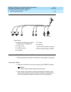
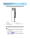
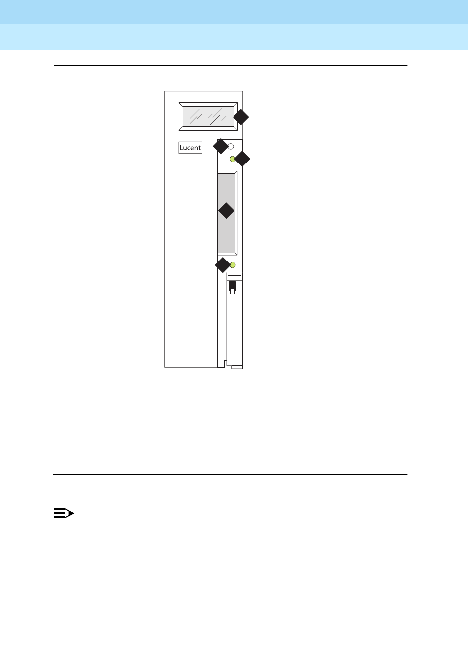
Figure 6-26. TN802B IP Interface faceplate
NOTE:
To properly seat the circuit pack, push firmly on the front of the faceplate
until the latch reaches the bottom rail of the carrier. Then close the latch
until it is fully engaged.
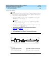
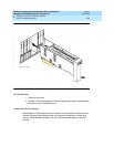
1. Insert the TN802B IP Interface into the rightmost of the three slots you
reserved for it (see Figure 6-27
).
When you plug in the TN802B IP Interface, the circuit pack starts to boot
and the LCD reads
PC Boot
then after about 3 to 4 minutes it changes to
IP TRK *
, the default mode.
Figure Notes
1. LCD display
2. Reset button (recessed)
3. Red board status LED
4. PCMCIA card slot
5. Yellow PCMCIA disk-in-use LED
1
2
3
4
5
fpdfmapd KLC 030899


