


DEFINITY Enterprise Communications Server Release 8.2
Upgrades and Additions for R8r
555-233-115
Issue 1
April 2000
Multicarrier G2 Universal Module to R8r EPN
5-100Critical Reliability
5
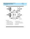
For Two Fiber-Remoted Expansion Port Networks
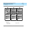
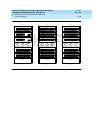
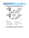
1. Behind control carrier A of PPN cabinet 1:
■ Install a lightwave transceiver on the cable connector at slot 1A02.
■ Connect a fiber optic cable to the transceiver just installed.
■ Route the cable to the cable tray and down, out of the cabinet,
through the cable manager to the PDS cross-connect facility.
■ Connect the fiber cable to the lightguide interconnect unit provided.
■ Carefully attach the fiber optic cable (with cable ties) to the wall of
the cable tray at the built-in cable tie positions.
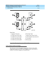
2. Behind control carrier A of EPN cabinet 3:
■ Install a lightwave transceiver on cable connector at slot 3A01.
■ Connect the fiber optic cable to the transceiver just installed.
■ Route the fiber cable to the cable tray and down, out of the cabinet,
through the cable manager to the PDS cross-connect facility.
■ Connect the fiber cable to the lightguide interconnect unit provided.
■ Carefully attach the fiber optic cable (with cable ties) to the wall of
the cable tray at the built-in cable tie positions.
■ Coil the surplus fiber optic cable and place it in the cable manager.
3. Behind control carrier B of PPN cabinet 1:
■ Install a lightwave transceiver on cable connector at slot 1B02.
■ Connect a fiber optic cable to the transceiver just installed.
■ Route the cable to the cable tray and down, out of the cabinet,
through the cable manager to the PDS cross-connect facility.
■ Connect the fiber cable to the lightguide interconnect unit provided.
■ Carefully attach the fiber optic cable (with cable ties) to the wall of
the cable tray at the built-in cable tie positions.
4. Behind port carrier B of EPN cabinet 3:
■ Install a lightwave transceiver on the cable connector at slot 3B02.
■ Connect the fiber optic cable to the transceiver just installed.
■ Route the cable to the cable tray and down, out of the cabinet,
through the cable manager to the PDS cross-connect facility.
■ Connect the fiber cable to the lightguide interconnect unit provided.
■ Carefully attach the fiber optic cable (with cable ties) to the wall of
the cable tray at the built-in cable tie positions.
■ Coil up the surplus fiber cable and place it in the cable manager.