


DEFINITY Enterprise Communications Server Release 8.2
Upgrades and Additions for R8r
555-233-115
Issue 1
April 2000
Adding or Removing Cabinet Hardware
6-32Install a New EPN Cabinet in an Existing System
6
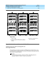
14. At the rear of the Expansion Control Carrier in position A in Cabinet 2,
install a lightwave transceiver onto Slot 1 (2A01).
15. Connect a 20-foot (6 m) fiber optic cable to the TX and RX connectors on
the transceiver. Be sure to label the cable.
16. At the rear of the Switch Node Carrier in position E in Cabinet 4, install a
lightwave transceiver onto Slot 20 (4E20).
17. Connect the 20-foot (6 m) fiber optic cable from the transceiver on the
Switch Node Carrier position E in Cabinet 4. Be sure the cable connected
to the TX connector on 1 transceiver is connected to the RX connector on
the other transceiver and vice versa.
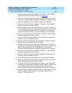
18. At the rear of the Port Carrier in position B in Cabinet 3, install a lightwave
transceiver onto Slot 2 (3A01).
19. Connect a 20-foot (6 m) fiber optic cable to the TX and RX connectors on
the transceiver. Be sure to label the cable.
20. At the rear of the Switch Node Carrier in position E in Cabinet 4, install a
lightwave transceiver onto Slot 3 (4E03).
21. Connect the 20-foot (6 m) fiber optic cable from the transceiver on the
Switch Node Carrier position E in Cabinet 4. Be sure the cable connected
to the TX connector on 1 transceiver is connected to the RX connector on
the other transceiver and vice versa.
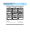
22. At the rear of the Expansion Control Carrier in position A in Cabinet 3,
install a lightwave transceiver onto Slot 2 (3B02).
23. Connect a 20-foot (6 m) fiber optic cable to the TX and RX connectors on
the transceiver. Be sure to label the cable.
24. At the rear of the Switch Node Carrier in position D in Cabinet 4, install a
lightwave transceiver onto Slot 3 (4D03).
25. Connect the 20-foot (6 m) fiber optic cable from the transceiver on the
Switch Node Carrier position D in Cabinet 4. Be sure the cable connected
to the TX connector on 1 transceiver is connected to the RX connector on
the other transceiver and vice versa.
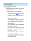
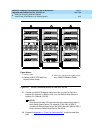
NOTE:
Continue connecting the fiber cables in this manner until all fiber
connections are made. Be sure to add links to PNs in alternating
order (20 and 2, 19 and 3, 18 and 4, and so forth).
26. Connect an H600-278 Metallic Cable from Slot 1 in the Expansion Control
Carrier in Cabinet 4 (4A01) to Slot 19 on the Switch Node Carrier in
position E in Cabinet 4 (4E19).