


DEFINITY Enterprise Communications Server Release 8.2
Upgrades and Additions for R8r
555-233-115
Issue 1
April 2000
Multicarrier G2 Universal Module to R8r EPN
5-79Critical Reliability
5
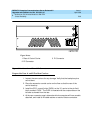
Remove Module Control Carriers A and B
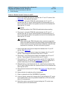
1. Remove the TDM/LAN cable from between the “A” and “B” carriers. See
Figure 5-23
. This cable will be reused.
2. Disconnect 1 end of the TDM/LAN cable (between the “A” and “D”
carriers) from the “A” carrier. Leave the other end connected to the “D”
carrier, and move the cable into a position so that it will not interfere with
removing the “A” carrier.
NOTE:
Note the position of the TDM/LAN cable before disconnecting.
3. Disconnect 1 end of the TDM/LAN cable (between the “B” and “C”
carriers) from the “B” carrier. Leave the other end connected to the “C”
carrier, and move the cable into a position so that it will not interfere with
removing the “B” carrier.
!
CAUTION:
When removing the TDM/LAN cables from a previously upgraded
carrier, be careful that none of the short pieces of shrink tubing come
off the 4 corner pins of the pin-field block. Otherwise, when the new
equipment is connected, -48 volts could short to ground.
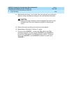
4. Remove and retain the 8 ground straps from between the “A” and “B”
carriers. See
Figure 5-24
.
5. Disconnect 1 end of the 8 ground straps from between the “A” and “D”
carriers. These straps will reconnect to the new “A” carrier.
6. Disconnect 1 end of the 8 ground straps from between the “B” and “C”
carriers. These straps will reconnect to the new “B” carrier.
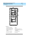
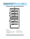
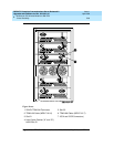
7. Disconnect the “P1” (small 9-pin) connector and the “P2” (large 38-pin)
connector from the “A” carrier. See
Figure 5-25
. Move the cables into a
position where they will not interfere with removing the carrier.
8. Slide the latch up, and disconnect the “P1” (small 9-pin) connector from
the “B” carrier. Move the cable into a position where it will not interfere with
removing the carrier.
9. Disconnect and remove the ICC cables. See
Figure 5-23
. They will not be
reused.
10. Remove the fan trim plate by pulling it straight off.
11. Clean or replace the air filter (403326820) if necessary.
12. In front of carrier, remove the 4 screws (top 2 first) holding the “B” carrier
to the cabinet frame. Use a long-handle screwdriver or 5/16-inch socket
with a 10-inch extension.
13. Behind the carrier, remove the 2 screws holding the “B” carrier’s rear
connector panel to the cabinet frame.