


DEFINITY Enterprise Communications Server Release 8.2
Upgrades and Additions for R8r
555-233-115
Issue 1
April 2000
Adding or Removing Cabinet Hardware
6-147Installing a 3150/3170 Channel Service Unit
6
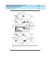
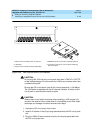
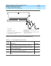
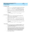
Figure 6-58. DS1 Converter Connections Using Double-Headed cable
1. Port carrier
2. DS1 converter connector
3. 50-pair female connector to DEFINITY System
4. 14-Inch (35.57 cm) “Y” cable
5. 50-Pin Male/50-pin female double-headed
connector cable
6. Quad cable (with 50-pin male connector) connects
to the channel service unit.
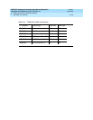
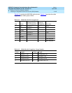
Table 6-14. “Y” cable Lengths (DS1 converter Only)
Length
(in/cm) Description Comcode
14/35.5 TN1754 to adjacent expansion interface circuit pack or
TN573B switch node interface circuit pack in same carrier
847245750
70/177.8 TN1754 to expansion interface circuit pack or switch node
interface in another carrier
847245778
14/35.5 TN1754 to fiber optic transceiver (DC-powered cabinets only).
This cable is for intercabinet cabling only.
847245777
14/35.5 TN1754 to adjacent TN570/B/C expansion interface circuit
pack
847747741
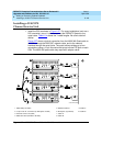
cydf010RPY090597
20 19 161718 15 14 13 12 11
10
09 08 07 06 05 04 03 02 01