


DEFINITY Enterprise Communications Server Release 8.2
Upgrades and Additions for R8r
555-233-115
Issue 1
April 2000
Fiber Link Administration
A-15Administer Fiber Links
A
NOTE:
The line equalization setting defaults to 2 and remains in effect until
changed by administration. Because incorrect equalizer settings
cause a potentially higher error rate on the DS1 facility, it is
necessary to provide the correct settings based on the distance to
the Network interface.
If it is a TN574 circuit pack, the default for all facilities is
1
.
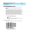
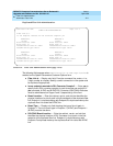
■ DS1CONV-2 Line Compensation
— Enter the line compensation (
1
to
5
)
in the A, B, C, and D columns under the DS1 Converter Facilities heading
for each DS1 facility connected to ENDPOINT-2 (see Table 6-15
). The DS1
line signal is pre-equalized at the transmitter so that DS1 line pulses are
the correct amplitude and shape when they reach the Network Interface.
The amount of equalization necessary is determined by the distance to
the Network Interface (when the endpoint supplies a DSX-1 interface) and
also by the type of wiring used to connect to the Network Interface. The
types of wiring allowed are 22-gauge ABAM (shielded twisted pair) cable,
24-gauge Premises Distribution System (PDS) wiring, and 26-gauge PDS
wiring.
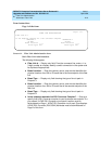
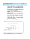
■ Facility A Circuit ID — Displays when the value in
Facility
Installed
for Facility A is
yes
. Enter up to 40 characters to identify the
cabinet, carrier, and slot of the DS1 Converter circuit pack’s physical
location.
Similarly, Facility B Circuit ID, Facility C Circuit ID, and Facility D Circuit ID
fields display for each of the DS1 Converter Facilities when
yes
is entered
in the corresponding Facility Installed field.
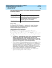
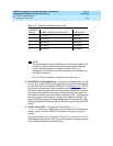
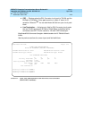
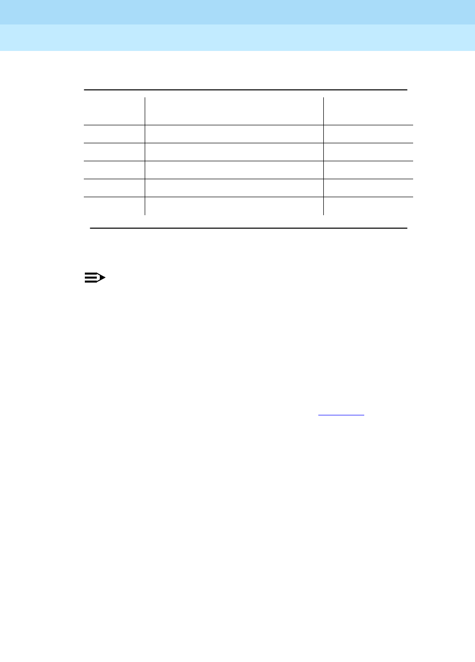
Table 6-15. Distance to DSX-1 Interface (feet
Equalizer
Setting 22 AWG ABAM & 24 AWG PDS 26 AWG PDS
1 1 to 133 0 to 90
2 133 to 266 90 to 180
3 266 to 399 180 to 270
4 399 to 533 270 to 360
5 533 to 655 360 to 450
Continued on next page